After the read of the 9 Main Antenna Performance Parameters article, you will know about:
What are the antenna performance parameters?
Antenna performance parameters 1. Resonance frequency
Antenna performance parameters 2. Gain
Antenna performance parameters 3. Bandwidth
Antenna performance parameters 4. Impedance
Antenna performance parameters 5. Radiation pattern
Antenna performance parameters 6. Characteristic impedance
Antenna performance parameters 7. Attenuation coefficient
Antenna performance parameters 8. Input impedance
Antenna performance parameters 9. Working frequency
There are many critical parameters that affect antenna performance, which can usually be adjusted during the antenna design process, such as resonance frequency, impedance, gain, aperture or radiation pattern, polarization, efficiency, and bandwidth.
In addition, the transmitting antenna has maximum rated power, and the receiving antenna has noise suppression parameters.
What are the antenna performance parameters?
Antenna performance parameters 1. Resonance frequency
The resonant frequency and electrical resonance are related to the electrical length of the antenna. The electrical length is usually the physical length of the wire divided by the ratio of the wave propagation speed in free space to the speed in the wire. The electrical length of the antenna is usually expressed by the wavelength.
Antennas are generally tuned at a certain frequency and are effective in a frequency band centered on this resonant frequency. But other antenna parameters (especially the radiation pattern and impedance) vary with frequency, so the resonant frequency of the antenna may only be close to the center frequency of these more important parameters.
The antenna can resonate at a frequency corresponding to the length of the target wavelength component number relationship. Some antennas are designed with multiple resonant frequencies, while others are relatively effective over a wide frequency band.
The most common broadband antenna is a log-periodic antenna, but its gain is much smaller than that of a narrowband antenna.
Antenna performance parameters 2. Gain
Gain refers to the logarithm of the ratio of the intensity of the antenna radiation pattern of the antenna’s strongest radiation directly to the intensity of the reference antenna. If the reference antenna is an omnidirectional antenna, the unit of gain is in dBi.
For example, the gain of the dipole antenna is 2.14dBi. Dipole antennas are also often used as reference antennas (this is because a perfect omnidirectional reference antenna cannot be manufactured). In this case, the gain of the antenna is in dBd.
Antenna gain is a passive phenomenon. The antenna does not increase excitation, but only redistributes it to radiate more energy in a certain direction than an omnidirectional antenna.
If the antenna gain is positive in some directions, its gain in other directions will be negative due to the conservation of energy of the antenna. Therefore, the gain that the antenna can achieve must be balanced between the antenna’s coverage and its gain.
For example, the gain of the dish antenna on the spacecraft is very large, but the coverage area is very narrow, so it must point accurately to the earth; while the broadcast transmitting antenna needs to radiate in all directions, its gain is very small.
The gain of a dish antenna is proportional to the aperture (reflection area), the surface accuracy of the antenna reflection surface, and the frequency of transmission/reception.
Generally speaking, the larger the aperture, the greater the gain, and the higher the frequency, the greater the gain, but the error of the surface accuracy at higher frequencies will result in a great decrease in gain.
Aperture and radiation patterns are closely related to gain.
Aperture refers to the cross-sectional shape of the beam in the direction of the highest gain, which is two-dimensional (sometimes the aperture is expressed as the radius of a circle approximated to the cross-section or the angle of the beam cone).
The radiation pattern is a three-dimensional graph representing gain, but usually, only the horizontal and vertical two-dimensional sections of the radiation pattern are considered.
The radiation pattern of a high-gain antenna is often accompanied by side lobes. Sidelobe refers to the beams other than the main lobe (the beam with the highest gain) in the gain.
When systems such as radars need to determine the direction of the signal, the sidelobe will affect the quality of the antenna. The sidelobe will also reduce the main lobe gain due to power distribution.
Gain refers to the ratio of the power density of the signal generated by the actual antenna and the ideal radiating element at the same point in space under the condition of equal input power.
It quantitatively describes the degree to which an antenna concentrates the input power and radiates it. The gain obviously has a close relationship with the antenna pattern. The narrower the main lobe of the pattern and the smaller the side lobe, the higher the gain.
The physical meaning of gain can be understood like this:
A signal of a certain size is generated at a certain point at a certain distance. If an ideal non-directional point source is used as the transmitting antenna, 100W input power is required, and a certain directional antenna with a gain of G = 13 dB = 20 is used as the transmitting antenna. When using an antenna, the input power is only 100/20 = 5W.
In other words, the gain of a certain antenna, in terms of the radiation effect in its maximum radiation direction, is the multiple of the input power amplification compared with an ideal point source without directionality.
The gain of the half-wave symmetrical oscillator is G=2.15dBi.
Four half-wave symmetrical oscillators are arranged up and down along the vertical line to form a vertical four-element array, with a gain of approximately G=8.15dBi (dBi unit indicates that the comparison object is an ideal point source with uniform radiation in all directions).
If a half-wave symmetric oscillator is used as the comparison object, the unit of gain is dBd.
The gain of the half-wave symmetrical oscillator is G=0dBd (because it is compared with itself, the ratio is 1, and the logarithm is zero.) The gain of the vertical quaternion array is about G=8.15–2.15=6dBd.
Antenna performance parameters Gain characteristics
⑴ The antenna is a passive device and cannot generate energy. The antenna gain is only the ability to effectively concentrate energy in a specific direction to radiate or receive electromagnetic waves.
⑵The antenna gain is produced by the superposition of dipole elements. The higher the gain, the longer the antenna length.
⑶ The higher the antenna gain, the better the directivity, the more concentrated the energy, and the narrower the lobe.
Antenna performance parameters 3. Bandwidth
The bandwidth of an antenna refers to the frequency range in which it works effectively, usually centered on its resonant frequency.
The antenna bandwidth can be increased by the following techniques, such as the use of thicker metal wires, the use of metal meshes to approximate thicker metal wires, antenna elements with thinner tips (such as in a feed horn), and a single integrated multi-antenna Components, use characteristic impedance to select the correct antenna.
Small antennas are usually easy to use but have unavoidable limitations in bandwidth, size, and efficiency.
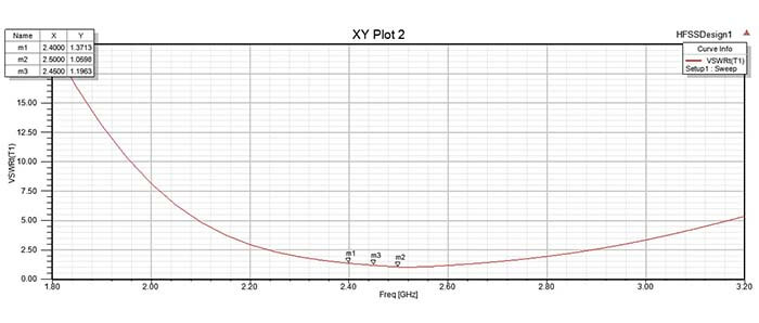
Antenna performance parameters 4. Impedance
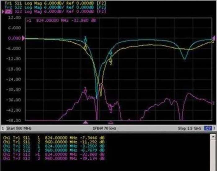
Impedance is similar to the refractive index in optics. Radio waves traveling through different parts of the antenna system (radio, feeder, antenna, free space) will encounter impedance differences.
At each interface, depending on the impedance matching, part of the energy of the electric wave will be reflected back to the source, forming a certain standing wave on the feeder. At this time, the ratio of the maximum energy to the minimum energy of the electric wave can be measured, which is called the standing wave ratio (SWR).
A standing wave ratio of 1:1 is ideal. A standing wave ratio of 1.5:1 is regarded as a critical value in low-energy applications where energy consumption is more critical.
The standing wave ratio of up to 6:1 can also appear in the corresponding equipment. Minimizing the impedance difference (impedance matching) of various interfaces will reduce the standing wave ratio and maximize the energy transmission between the various parts of the antenna system.
The complex impedance of an antenna relates to the electrical length of the antenna during operation. By adjusting the impedance of the feeder, that is, the feeder is used as an impedance converter, the impedance of the antenna can be matched with the feeder and the radio.
It is more common to use antenna tuners, baluns, impedance converters, matching networks including capacitors and inductors, or matching sections such as gamma matching.
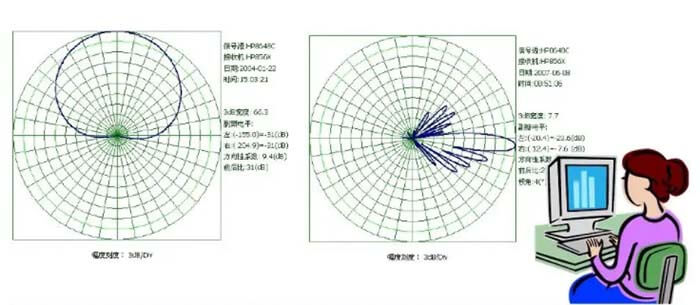
Antenna performance parameters 5. Radiation pattern
The half-wave dipole antenna (same as above) gain (dBi) radiation pattern is a graphical description of the relative field strength of the antenna emitted or received. Since the antenna radiates to a three-dimensional space, several figures are needed to describe it.
If the antenna radiation is symmetrical with respect to a certain axis (such as dipole antennas, helical antennas, and some parabolic antennas), only one pattern is required.
Different antenna suppliers/users have different standards and drawing formats for the pattern.
Antenna performance parameters 6. Characteristic impedance
The ratio of voltage to current everywhere on an infinite transmission line is defined as the characteristic impedance of the transmission line, which is represented by Z。. The calculation formula of the characteristic impedance of the coaxial cable is
Z。=〔60/√εr〕×Log (D/d) [Ou].
In the formula, D is the inner diameter of the coaxial cable outer conductor copper mesh; d is the outer diameter of the coaxial cable core wire;
εr is the relative permittivity of the insulating medium between conductors.
Usually Z。= 50 ohms, there are also Z。= 75 ohms.
It is not difficult to see from the above formula that the characteristic impedance of the feeder is only related to the conductor diameters D and d and the dielectric constant εr of the medium between the conductors, but has nothing to do with the length of the feeder, the operating frequency and the load impedance connected to the feeder terminal.
Antenna performance parameters 7. Attenuation coefficient
Signal transmission in the feeder cable, in addition to the resistive loss of the conductor, there is also the dielectric loss of the insulating material.
These two losses increase with the increase of the length of the feeder and the increase of the operating frequency. Therefore, the length of the feeder should be shortened in a reasonable layout.
The magnitude of the loss per unit length is expressed by the attenuation coefficient β, and its unit is dB/m (decibel/meter), and the unit in the cable technical manual is mostly dB/100 m (decibel/100m).
Suppose the power input to the feeder is P1 and the power output from the feeder of length L(m) is P2, the transmission loss TL can be expressed as:
TL = 10 ×Lg (P1 /P2) (dB)
The attenuation coefficient is
β = TL / L (dB / m)
For example, in NOKIA 7/8-inch low-consumption cable, the attenuation coefficient at 900MHz is β= 4.1 dB / 100 m, which can also be written as β=3 dB / 73 m, that is to say, the signal power of 900MHz frequency, every 73 m For long cables of this type, the power is reduced by half.
For ordinary non-low-consumption cables, for example, SYV-9-50-1, the attenuation coefficient at 900MHz is β = 20.1 dB / 100 m, which can also be written as β = 3dB / 15 m, that is, a signal with a frequency of 900MHz The power is reduced by half for every 15 m of this cable.
Antenna performance parameters 8. Input impedance
Definition
The ratio of the signal voltage at the antenna input terminal to the signal current is called the input impedance of the antenna.
The input impedance has a resistance component Rin and a reactance component Xin, that is, Zin = Rin + j Xin.
The presence of the reactance component will reduce the antenna’s extraction of signal power from the feeder. Therefore, the reactance component must be as zero as possible, that is, the input impedance of the antenna should be as pure as possible.
In fact, even a well-designed and well-tuned antenna has a small reactance component in its input impedance.
The input impedance is related to the structure, size, and working wavelength of the antenna. The half-wave symmetrical oscillator is the most important basic antenna, and its input impedance is Zin = 73.1+j42.5 (Europe).
When the length is shortened by (3~5)%, the reactance component can be eliminated and the input impedance of the antenna is pure resistance. At this time, the input impedance is Zin = 73.1 (Euro), (nominal 75 ohms).
Note that strictly speaking, the purely resistive antenna input impedance is only for the point frequency.
By the way, the input impedance of the half-wave folded vibrator is four times that of the half-wave symmetrical vibrator, that is, Zin = 280 (ohm), (nominal 300ohm).
What is interesting is that for any antenna, people can always adjust the antenna impedance to make the imaginary part of the input impedance very small and the real part quite close to 50 ohms within the required operating frequency range, so that the input impedance of the antenna is Zin = Rin = 50 ohms, which is necessary for good impedance matching between the antenna and the feeder.
Antenna performance parameters 9. Working frequency
Regardless of whether it is a transmitting antenna or a receiving antenna, they always work within a certain frequency range (bandwidth). There are two different definitions for the bandwidth of the antenna:
One type refers to the working frequency bandwidth of the antenna under the condition of standing wave ratio SWR ≤ 1.5;
Another one is the bandwidth within the range of 3 decibels of antenna gain reduction.
In mobile communication systems, it is usually defined according to the former one. Specifically, the bandwidth of the antenna is the operating frequency range of the antenna when the standing wave ratio SWR of the antenna does not exceed 1.5.
Generally speaking, there are differences in antenna performance at various frequency points within the working frequency bandwidth, but the performance degradation caused by this difference is acceptable.
C&T RF Antennas Inc has more than ten years of antenna research and development and manufacturing. All antennas undergo rigorous inspection and testing before being delivered to customers.
C&T RF Antennas Inc provides the IoT & M2M antennas with other radio frequencies such as 169MHz, 230MHz, 315MHz, 433MHz, 868MHz, 915MHz, VHF&UHF, Lora, NB-IoT, ADS-B, GSM, GNSS, Wifi 2.4GHz, 5.8GHz, 2G 3G 4G LTE, GPS, 5G NR, etc.
C&T RF Antennas Inc provides the indoor-outdoor antenna with many antenna types such as Dipole Antennas, Whip Antennas, Marine Antennas, Router Antennas, MIMO Antennas, PCB Antennas, FPC Antennas, Spring Antennas, etc.
Please contact the C&T RF Antennas Inc team about antenna design and production.
Besides the 9 Main Antenna Performance Parameters article, you may also be interested in the below articles.
WiFi vs. Cellular, Is WiFi Better Than Cellular?
4G vs. 5G: What is the difference between 4G and 5G?
How to Choose the Best Antenna for Lora?