After the read, you will learn:
What is antenna feed system
Antenna system introduction
Feeder introduction
The principle of power feed system
Antenna feed system FAQ
What Is An Antenna Feed System?
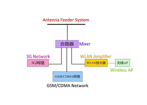
The antenna feed system refers to the system in which the antenna radiates electromagnetic waves to the surrounding space.
Electromagnetic waves are composed of electric and magnetic fields. It is stipulated that the direction of the electric field is the polarization direction of the antenna. The generally used antenna is single-polarized. The figure below shows two basic single polarization situations, vertical polarization and horizontal polarization.
First, antenna system introduction
Antennas have different radiation or receiving capabilities in different directions in space, which is the directivity of the antenna.
To measure the directivity of an antenna, a pattern is usually used. On a horizontal plane, an antenna with no maximum direction for radiation and reception is called an omnidirectional antenna, and an antenna with one or more maximum directions is called a directional antenna.
Since omnidirectional antennas are non-directional, they are mostly used in the central station of point-to-multipoint communication.
Since the directional antenna has the largest radiation or receiving direction, the energy is concentrated, and the gain is higher than that of the omnidirectional antenna. It is suitable for long-distance point-to-point communication. At the same time, due to its directivity, the anti-interference ability is relatively strong.
The antenna feeder system mainly includes two categories, antenna and feeder system.
1. Antenna
Mainly includes
The price is moderate, the installation is convenient, and the gain is moderate. It is suitable for installation on moving vehicles or adsorbed on metal objects. Generally, the gain is 2.6dB, 5dB, etc.
The price is moderate, the installation is convenient, and the gain is the same as the suction cup antenna. When installed outside the metal box, it cannot be removed from the outside of the box, so it is called the anti-theft antenna.
C) Low gain omnidirectional antenna
The gain is 3.5dB, and the installation requires a fixed bracket, which is suitable for long-distance multipoint transmission.
D) High gain omnidirectional antenna
The gain is 8.5dB, and the installation requires a fixed bracket, which is suitable for long-distance multipoint transmission.
E) Directional antenna
The gain is very high, 12dB and the installation requires a fixed bracket, which is suitable for long-distance transmission in a fixed direction.
2. Feeder cable
Mainly includes
A) The feeder loss of 50-3 (impedance 50Ω, section 3) is 0.2dB/m.
B) 50-7 (impedance 50Ω, cross-section 7) feeder loss is 0.1dB/m
C) The feeder loss of 50-9 (impedance 50Ω, cross-section 9) is 0.07dB/m.
The feeder cable is an important device connecting the radio and the antenna. Feeders of different thicknesses and qualities will have a great impact on the communication distance.
The signal is transmitted in the feeder, in addition to the resistive loss of the conductor, there is also the dielectric loss of the insulating material. These two losses increase with the increase of the length of the feeder and the increase of the operating frequency.
Therefore, the length of the feeder cable should be shortened as much as possible.
Second, the principle of power antenna feeder system
1. Characteristic impedance
The ratio of voltage to current everywhere on an infinite transmission line is defined as the characteristic impedance of the transmission line, which is represented by Z0.
The calculation formula of the characteristic impedance of the coaxial cable is: Z0=〔60/√εr〕×Ln( D/d) [Ou]
In the formula, D is the inner diameter of the coaxial cable outer conductor copper mesh; d is the outer diameter of the coaxial cable core wire; εr is the relative permittivity of the insulating medium between the conductors.
Usually Z0 = 50 ohms, and there are also Z0 = 75 ohms.
It is not difficult to see from the formula that the characteristic impedance of the feeder is only related to the ratio of the conductor diameters D and d and the dielectric constant εr of the medium between the conductors, but has nothing to do with the length of the feeder, the operating frequency and the impedance of the load connected to the feeder terminal.
2. Dielectric loss
Signal transmission in the feeder, in addition to the resistive loss of the conductor, there is also the dielectric loss of the insulating material. These two losses increase with the increase of the length of the feeder and the increase of the operating frequency. Therefore, the length of the feeder should be shortened as much as possible.
The magnitude of the loss per unit length is expressed by the attenuation coefficient β, and its unit is dB/m (decibel/meter), and most of the units in the cable technical manual use dB/100 m (decibel/100m). Suppose the power input to the feeder is P1, and the power output from the feeder of length L(m) is P2, the transmission loss TL can be expressed as TL = 10 × Lg (P1 /P2) (dB)
The attenuation coefficient is: β = TL / L (dB / m)
For example, in NOKIA 7/8-inch low-consumption cable, the attenuation coefficient at 900MHz is β = 4.1 dB / 100 m, which can also be written as β = 3 dB / 73 m, that is, the signal power at the frequency of 900MHz, every 73 m For long cables of this type, the power is reduced by half.
For ordinary non-low-consumption cables, for example, SYV-9-50-1, the attenuation coefficient at 900MHz is β = 20.1 dB / 100 m, which can also be written as β = 3 dB / 15 m, which means that the frequency is 900MHz The signal power is reduced by half every time a 15 m long cable is passed.
3. Matching concept
What is matching? Simply put, when the load impedance ZL connected to the feeder terminal is equal to the feeder characteristic impedance Z0, the feeder terminal is called a matched connection.
During matching, only the incident wave transmitted to the terminal load exists on the feeder, and there is no reflected wave generated by the terminal load. Therefore, when the antenna is used as a terminal load, the matching can ensure that the antenna obtains all signal power.
When the antenna impedance is 50 ohms, it matches the 50-ohm cable, and when the antenna impedance is 80 ohms, it does not match the 50-ohm cable.
If the diameter of the antenna element is thick, the input impedance of the antenna changes little with frequency, and it is easy to keep matching with the feeder. At this time, the working frequency range of the antenna is wider. On the contrary, it is narrower.
In actual work, the input impedance of the antenna will also be affected by surrounding objects. In order to make a good match between the feeder and the antenna, it is necessary to properly adjust the local structure of the antenna or install a matching device when setting up the antenna.
4. Reflection loss
It has been pointed out earlier that when the feeder and the antenna are matched, there is no reflected wave on the feeder, only the incident wave, that is, the feeder transmits only the waves traveling in the direction of the antenna.
At this time, the voltage amplitude and current amplitude everywhere on the feeder are equal, and the impedance at any point on the feeder is equal to its characteristic impedance.
When the antenna and the feeder do not match, that is, when the antenna impedance is not equal to the characteristic impedance of the feeder, the load can only absorb part of the high-frequency energy transmitted on the feeder, but not all of it. The unabsorbed part of the energy will be reflected back to form a reflected wave.
When the voltage standing wave ratio is not matched, there are incident waves and reflected waves on the feeder. Where the incident wave and the reflected wave have the same phase, the voltage amplitude adds up to the maximum voltage amplitude Vmax, forming an antinode;
Where the incident wave and the reflected wave have opposite phases, the voltage amplitude subtracts from the minimum voltage amplitude Vmin, forming a node. The amplitude values of other points are between the antinode and the node. This composite wave is called a traveling standing wave.
The ratio of the reflected wave voltage to the incident wave voltage amplitude is called the reflection coefficient.
Reflected wave amplitude (ZL-Z0)
Incident wave amplitude (ZL+Z0)
The ratio of the antinode voltage to the amplitude of the node voltage is called the standing wave coefficient, also called the voltage standing wave ratio, which is denoted as VSWR
Antinode voltage amplitude Vmax (1+R)
Nodal voltage amplitude Vmin (1-R)
The closer the terminal load impedance ZL and the characteristic impedance Z0 are, the smaller the reflection coefficient R, and the closer the standing wave ratio VSWR is to 1, the better the matching.
The antenna feed system is the collective name of the antenna system and the feeder system.
Third, antenna feeder system FAQ
Antenna feeder system FAQ 1, What is the working principle and function of the antenna?
Answer:
The antenna is an indispensable part of wireless communication, and its basic function is to transmit and receive radio waves. When transmitting, the high-frequency current is converted into electromagnetic waves; when receiving, the electromagnetic waves are converted into high-frequency current.
Antenna feeder system FAQ 2, How many types of antennas are there?
Answer:
There are many types of antennas, and there are mainly the following classification methods:
According to usage, it can be divided into base station antennas and mobile portable antennas.
According to the working frequency band, it can be divided into the ultra longwave, long wave, medium wave, short wave, ultra-short wave, and microwave;
According to its direction, it can be divided into omnidirectional and directional antennas;
Antenna feeder system FAQ 3, How to choose an antenna?
Answer:
The antenna is an important part of the communication system, and its performance directly affects the indicators of the communication system. The user must first pay attention to its performance when choosing an antenna. Specifically, there are two aspects, the first choice of antenna type; the second choice of the electrical performance of the antenna.
The significance of selecting the antenna type is whether the pattern of the selected antenna meets the requirements of radio wave coverage in the system design;
The requirement for selecting the electrical performance of the antenna is to select whether the electrical indicators such as the frequency bandwidth, gain, and rated power of the antenna meet the system design requirements.
Therefore, it is best for users to contact the antenna manufacturer for consultation when choosing an antenna.
Antenna feeder system FAQ 4, What is the gain of an antenna?
Answer:
Gain is one of the main indicators of the antenna. It is the product of the directional coefficient and the efficiency and is the performance of the antenna radiated or received. The choice of gain depends on the requirements of the system design for the radio wave coverage area.
Simply put, under the same conditions, the higher the gain, the longer the radio wave propagation distance. Generally, base station antennas use high-gain antennas, and mobile station antennas use low-gain antennas.
Antenna feeder system FAQ 5, What is the voltage standing wave ratio?
Answer:
When the antenna input impedance is inconsistent with the characteristic impedance of the feeder, the reflected wave generated and the incident wave are superimposed on the feeder to form a magnetic wave.
The ratio of the maximum value and the minimum value of the adjacent voltage is the voltage standing wave ratio, which is the test feeder The basis of transmission efficiency is that the voltage standing wave ratio is less than 1.5, and the voltage standing wave ratio at the operating frequency is less than 1.2.
If the voltage standing wave ratio is too large, the communication distance will be shortened, and the reflected power will return to the transmitter power amplifier part, which is easy to burn out, affecting the normal operation of the communication system.
Voltage standing wave ratio 1.0 1.1 1.2 1.5 2.0 3.0
Reflected power% 0 0.2 0.8 4.0 11.1 25.0
Transmission power% 100 99.8 99.2 96 88.9 75.0
Antenna feeder system FAQ 6, What is the directivity of an antenna?
Answer:
Antennas have different radiation or receiving capabilities in different directions in space. This is the directivity of the antenna.
To measure the directivity of an antenna, a pattern is usually used. On a horizontal plane, an antenna with no maximum direction for radiation and reception is called an omnidirectional antenna, and an antenna with one or more maximum directions is called a directional antenna.
Since omnidirectional antennas are non-directional, they are mostly used in the central station of point-to-multipoint communication. Since the directional antenna has the largest radiation or receiving direction, the energy is concentrated, and the gain is higher than that of the omnidirectional antenna.
It is suitable for long-distance point-to-point communication. At the same time, because of its directivity, it has a strong anti-interference ability.
Antenna feeder system FAQ 7, How to understand the working bandwidth of the antenna?
Answer:
The electrical parameters of the antenna are generally related to the operating frequency, and the allowable frequency variation range of the electrical parameters is guaranteed to be the operating frequency bandwidth of the antenna.
Generally, the working bandwidth of an omnidirectional antenna can reach 3-5% of the working frequency range, and the working bandwidth of a directional antenna can reach 5-10% of the working frequency.
Antenna feeder system FAQ 8, How to choose cable and cable length?
Answer:
Mobile communication systems often use coaxial cables with a characteristic impedance of 50 ohms as feeders. In order to effectively transmit radio waves to the antenna interface, the transmission loss of the feeder should be minimized. Transmission loss depends on the diameter and length of the cable.
The larger the diameter of the cable at the same frequency, the smaller the loss, and the longer the cable, the greater the loss. In principle, the transmission loss of the cable should not exceed 3 decibels. The following table lists the attenuation value (db/m) of commonly used cables. Users can choose the cable type and length reasonably according to their own conditions.
Frequency model 150MHz 400MHz 900MHz
SYV-50-7 0.121 0.203 0.295
CTC-50-7 0.060 0.100 0.165
CTC-50-9 0.050 0.085 0.135
CTC-50-12 0.040 0.060 0.105
Imported 10D-FB 0.040 0.070 0.110
Antenna feeder system FAQ 9, How to choose the antenna installation location?
Answer:
Due to the influence of terrain and environment, the electromagnetic wave received by the antenna is a superposition of direct waves, reflected waves, and scattered waves. The result determines the amplitude and phase of the field strength at the receiving point and directly affects the application effect of the antenna.
Therefore, the following aspects should be paid attention to when choosing the antenna installation position:
1) The antenna’s transmitting or receiving direction should avoid obstacles (buildings, towers, bridges, etc.);
2) The antenna installation location should be as far away as possible from interference sources (high-voltage lines, routes, iron towers, highways, etc.);
3) Antennas should be erected as far as possible at nearby vantage points:
4). If there are several antennas working on the same tower, special attention should be paid to the left, right, and up and down spacing between them to prevent mutual coupling from affecting system performance.
Antenna feeder system FAQ 10, How to install the antenna feeder system?
Answer:
First assemble the antenna, feeder, and supporting parts according to the requirements of the product description, and then fix the antenna on the antenna bracket of the tower pole with clamps at the supporting position of the antenna, and make the parallel distance between the antenna and the tower pole greater than the wavelength used, To reduce the influence of the tower pole on the antenna performance.
At the antenna port, connect the feeder cable connector (or cable head) to the antenna, and bend a ring with a diameter of about fifty times the diameter of the feeder cable to fix it on the antenna bracket to avoid direct force on the connector disconnected or damaged.
Antenna feeder system FAQ 11, How to waterproof the antenna system?
Answer:
The antenna and the feeder are mainly connected by the connector. Self-adhesive rubber sealing tape is used. After it is stretched, it is wound on the connector in a half-lap form, which can play a good sealing and waterproof effect. In addition, bend a waterproof bend where the feeder enters the room to prevent rainwater from entering the indoor equipment along the feeder.
Antenna feeder system FAQ 12, How to detect the antenna feeder system?
Answer:
After the antenna feeder system is set up, it should be tested by professional and technical personnel using special testing equipment. Usually, a through-type power meter can be connected in series between the transmitter and the antenna feeder system to check the transmitter power and reflected power of the equipment to determine whether the system is working properly.
Besides the What Is An Antenna Feed System article, you may also be interested in the below articles.
What is the difference between WIFI and WLAN?
Summary of 41 Basic Knowledge of LTE
What Is The 5G Network Slicing?
2 Responses