WE FACILITATE GLOBAL CONNECTION

Why us?

The C&T RF antennas Inc is an innovative and creative company specializing in the design and supply of multiband antenna solutions for telemetry and telematics applications. Our experience covers a wide range of antenna products from miniature handset antennas to wireless access point antennas and a variety of solutions in between.

We offer a range of standard products in the GSM, Cellular, ISM, GPS, and Wireless LAN frequency bands to reduce the time and cost of designing custom antennas into wireless products and devices.

The C&T RF Antennas Inc OEM Capability

R&D
We have a professional and experienced R&D team that can help to design and develop the planning of your project, Making ourselves be best, we promise to invest in keeping innovating continually
Keep customer’s design concepts, drawings, and documents
Exact communication to understand customer’s requirements
Design and development planning

Strength
Professional technical support
The complete quality control process
Complete producing plan
Complete testing equipment
Prompt reply within 24 hours
Well trained and aggressive staff


Hot Sale Products

antenna gain range

C&T RF Antennas Inc's antennas have passive and active from 0dBi to 45dBi gain range. High-Gain Omni-Directional Antenna is designed to expand the existing wireless networks without upgrading the device.

antenna frequncy range

C&T RF Antennas Inc's antenna products are from 100MHz to 6GHz frequency range. we have the extra-wide band 400MHz-6GHz antenna products.

Antenna Design And Custom

C&T RF Antennas Inc's antenna design and customization service is focused on the new style with the purpose of customizing antennas according to the profile and function of products.

Wireless Solutions

C&T RF Antennas Inc is prepared to add wireless capability to your existing network. Our antenna products are very suitable for the wireless, IoT, M2M industries.

Product Categories

Omni-directional antennas radiate 360° in the horizontal plane around the antenna, and peak gain is usually on the horizon.

An omnidirectional antenna is a wireless transmitting or receiving antenna that radiates or intercepts radio-frequency (RF) electromagnetic fields equally well in all horizontal directions in a flat, two-dimensional (2D) geometric plane. Omnidirectional antennas are used in most consumer RF wireless devices, including cellular telephone sets and wireless routers.

C&T RF Antennas Inc has the omnidirectional antennas with dipole antennas, router antennas, rubber duck antennas, waterproof antennas, fiberglass antennas, PCB antennas, etc.

A directional antenna or beam antenna is an antenna that radiates or receives greater power in specific directions allowing increased performance and reduced interference from unwanted sources.

A directional transmitting antenna is used to focus the wave into a narrow beam, which is directed toward a single receiver site. In either case the transmitted electromagnetic wave is picked up by a remote receiving antenna and reconverted to an electric current.

Directional antennas primarily receive and transmit energy in one direction. The most common type of directional antenna is the Yagi, it’s usually used as a TV aerial and promotes energy in one direction, using multiple prongs to encourage overall gain. Directional antennas are good for home/business use as you can tune the system for optimal coverage. With a directional antenna, the more focused the energy (the smaller the percentage of 360 degrees that the signal radiates,) the larger it’s the reachable distance.

C&T RF Antennas Inc has the directional antennas with Yagi antennas, RFID antennas, sector antennas, panel antennas, patch antennas, etc.

IoT

Cellular is the most common service used for the internet of things which is the network of physical devices, vehicles, home appliances, and others. IoT and the Cellular service enables these things to connect and exchange data.

M2M

Machine to machine communication can include industrial instrumentation, enabling a sensor or meter to communicate the data it records to application software that can use it.

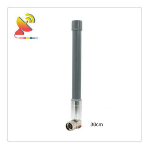
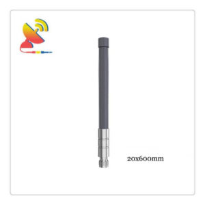
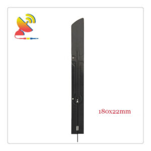
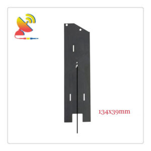
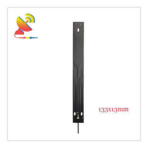
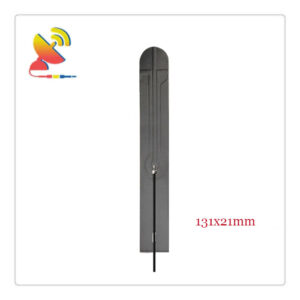
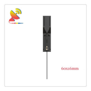
Antennas For IoT & M2M Applications

C&T RF Antennas Inc develops new antennas for 5G, 4G, NB-IoT, and LTE, addressing the wide frequency band and various bandwidth demands from cellular Internet of Things (IoT) devices.

They are able to provide a variety of band solutions ranging from 600MHz to 6000MHz/6GHz.

Depending on their system architecture, customers can choose new antennas with different mounting types (e.g. board mount, embedded, external or terminal antenna), cable length, and connector options. These antennas can be easily integrated to end devices since no tuning is needed and C&T RF Antennas Inc can offer service for embedding and even complex multiple antennas assemblies.

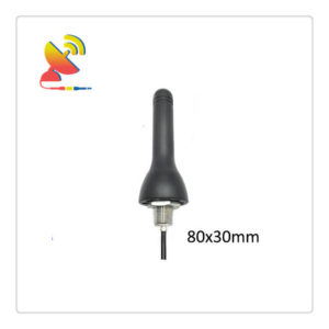
C&T RF Antennas Inc develops customer-specific antennas for the automotive and commercial vehicle industry as well as for M2M markets. Major carmakers rely on C&T RF Antennas Inc to provide the cellular antennas for their connected car solutions.

The antennas are also available as standard aftermarket products for vehicles and other mobile and stationary objects. For voice and data transmission, our antennas cover the full frequency ranges of GSM, UMTS, and LTE.

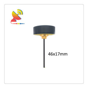
By investing in new test equipment C&T RF Antennas Inc is also well prepared for the upcoming 5G standard. Beyond that, we can offer cellular antennas also in combination with other services as e.g. GNSS, WLAN, Bluetooth, etc. in one design.

For use in vehicles, we offer variable designs for different interior and exterior installation spaces in dry or moisture-prone areas: short rod antennas, combo antennas, flat blade antennas, integrated antenna systems with flexible connection geometry (unconnected cable end or direct connector).

C&T RF Antennas Inc offers a broad selection of standard antennas and an impressive capability for custom antenna solutions; we work closely with customers to achieve successful integration solutions.
Our LDS antennas can save valuable space in your application by integrating high frequency, mechanical and electrical functionality into one component.

Whether you work on communications equipment or consumer devices, IoT, or machine-to-machine (M2M) applications, or applications in the connected home space – our antenna specialists can work with you to develop the right antenna solution for your design.

The high-speed transmission, low latency, and large-scale data communication of 5G can support massive consumer applications to achieve real-time and high reliability.

5G will extend the range of frequencies used for mobile communication in legacy LTE/4G systems as well as leverage the new Radio Access Technology for 5G.

5G innovation will enable an era of connectivity like never before. Anticipated experiences from autonomous driving, tactile internet, Ultra HD video, and VR based immersive technologies. Capacity-hungry communications will see demands for higher throughput, better spectral efficiency, ultra-low latency, and over 100 times the current number of connections.

C&T RF Antennas Inc is continuously at the forefront of wireless antenna technologies and we have various 5G antenna products to meet these demands in a range of applications.

Our range of internal and external 5G antennas. At C&T RF Antennas Inc you can work with our engineers to have the antenna tested, customized, and even certified for your needs.

Custom 5G antenna solutions can be provided. Please do not hesitate to contact our customer services team for more information.

C&T RF Antennas Inc has a wide range of 4G Antennas for use with our range of 4G routers, IoT, M2M, smart devices. These 4G LTE Antennas will help improve signal reception when locating your 4G LTE Router in a position with a poor 4G signal. Many of these 4G Antennas will also work with existing 3G frequencies making them multi-purpose 3G and 4G Antennas.

We supply reliable, industrial-grade 2G / 3G / 4G LTE Antennas to provide cost-effective mobile broadband connectivity for your CCTV, Energy, Remote Media, or Building Management application.

C&T RF Antennas Inc’s 698~2700 MHz Antennas offer excellent performance that covers for 2G/3G/4G/LTE cellular networks.

The antennas are well suited for DAS (Distributed Antenna Systems) and 802.11a/b/g/n and 802.11ac WiFi applications.

These 698~2700 MHz Antennas are available in patch, omnidirectional, ceiling mount, sector, and LPDA.

4G LTE is a standard for wireless communication of high-speed data for data terminal s and mobile phones. It is based on the GSM/EDGE and UMTS/HSPA network technologies, increasing the capacity and speed using a different radio interface together with network improvements.  

Buy 3G / 4G antennas for your M2M Communications – enabling YOU to connect to YOUR Smart Devices.

C&T RF Antennas Inc develops numerous cellular antennas for mobile communication in the automotive industry, the commercial vehicle and logistics sector, and M2M applications.

Applications: telephony, data communication, data exchange

Services/frequency ranges: frequency ranges of LTE low band to LTE high band (GSM, UMTS, LTE)

Installation spaces: variable designs for different interior and exterior installation spaces (dry and moisture-prone areas)

Designs: the large portfolio of short rod antennas, combination antennas, flat blade antennas, patch antennas, integrated antennas with flexible connection geometry (unconnected cable end or direct connector) for integration in different installation spaces.

C&T RF Antennas Inc supplies a complete range of 2G 3G 4G cellular antennas for 2G 3G and 4G applications, now with 5G, supporting UMTS, GSM, GPRS, AMPS, PCS, EDGE, CDMA, WCDMA, and AWS. These antennas support a variety of applications profiles including mobile, fixed-site, and temporary fit.

C&T RF Antennas Inc provides a variety of high performance, Low PIM 3G, 4G/LTE, and 5G antennas for superior speed, throughput, and seamless mobility.

iDAS, oDAS, and Small cell Antennas

Indoor & Outdoor Panel & Sector Antennas

Fiberglass Omnidirectional Antennas

5G Massive MIMO Solutions

Embedded and Integrated Antennas

Patented Phantom low-profile antennas

Multiband SISO and MIMO

Low profile antennas

A car antenna is used as a part of the radio system to amplify the signals and improve the overall sound quality. It is an indispensable part to ensure that the signal is clear and consistent, ensuring the best experience for users.

Moreover, a hidden antenna is not only small and portable but it also blends well with the surrounding. The car antenna is dedicated to any radio owners who want to build a better system in your own vehicles. A car antenna, which can be any electronic structure that is made to radiate or receive radio signals and other electromagnetic waves, is a must for every car.

The C&T RF Antennas Inc public transportation antennas are specifically designed to serve the needs for installations on trains, tram metros buses, and heavy trucks. The C&T RF Antennas Inc offers a wide range of products from the communications and positioning antenna on the rooftop to the low profile WiFi antennas in the vehicle. The adjacent range of semi-stationary and stationary antennas are complementing the series with M2M and WiFi antennas.

C&T RF Antennas Inc offers a full spectrum of GNSS Antennas for GPS, GLONASS, BeiDou, and Galileo antennas for a variety of applications including fleet management, asset tracking, vehicle tracking, and personnel tracking. Our low-profile, high-performance and cost-effective designs provide rugged reliability in the harshest environments.

Multi-band GPS solutions

Permanent, magnetic, and shock-absorbing mounting options

Applications: Public Safety, Fleet Tracking, Wearables, M2M, Vehicular

GPS antenna performance can significantly vary based on your specific enclosure requirements. We are here to help you design a custom GPS solution or select the best GPS antenna for your application, so please contact us with any questions you have.

A dipole antenna is the simplest type of radio antenna, consisting of a conductive wire rod that is half the length of the maximum wavelength the antenna is to generate. This wire rod is split in the middle, and the two sections are separated by an insulator. Each rod is connected to a coaxial cable at the end closest to the middle of the antenna.

There are three types of dipoles:

Ideal half-wavelength dipole

Folded dipole

Radiofrequency voltages are applied to dipole antennas at the center, between the two conductors. 

C&T RF Antennas Inc has the indoor-outdoor dipole antennas, also with the Omni dipole antennas, combo dipole antennas, etc.

If your 3G or 4G Router is located in a position with a poor mobile broadband signal then you may want to use a different 3G/4G Antenna – for example – your 4G router is located indoors with a poor 4G signal, but there is a good 4G signal outdoors – in this example, you could install an outdoor MiMo 4G Antenna where there is a better signal and connect this to your 4G router indoors.

The extra gain supplied by the high gain outdoor 4G antenna will compensate for the extra signal loss along the length of the antenna cable so the installation of an outdoor 4G antenna would provide a similar service as though you had installed your router outdoors were the better 4G signal was available. These are not booster antennas, they work on the principle that the signal will be better in the location of the antenna compared to the router.

C&T RF Antennas Inc’s Full band 2G / 3G / 4G Antenna range work with all of our 3G and 4G routers and work with all GSM/2G/3G/GRPS/HSPA/UMTS/4G/LTE mobile network services and are available to suit a variety of installation criteria.

C&T RF Antennas Inc newly launched 5G antennas are also available for direct selling or design.

MIMO is effectively a radio antenna technology. As it uses multiple antennas at the transmitter and receiver to enable a variety of signal paths to carry the data, choosing separate paths for each antenna to enable multiple signal paths is being used.

By using MIMO, these additional paths can be used to advantage. In wireless, the term MIMO is referred to the use of multiple antennas at the transmitter and the receiver. In modern usage, MIMO specifically refers to a practical technique for sending and receiving more than one data signal simultaneously. Over the same radio, the channel has exploited multipath propagation. 

MIMO technology has been standardized for wireless LANs, 3G mobile phone networks, and 4G LTE mobile phone networks and is now in widespread commercial use. 

According to the number of antennas of base stations and mobile phones, they can be divided into four types: SISO, SIMO, MISO, and MIMO. Their English meanings are as follows:

① SISO: Single Input Single Output

② SIMO: Single Input Multiple Output

③ MISO: Multiple Input Single Output

④ MIMO: Multiple Input Multiple Output

C&T RF Antennas Inc has the omnidirectional 4G / 5G MIMO antennas and directional 4G / 5G MIMO antennas in stock, and ready for MIMO antenna design.

The C&T RF antennas Inc’s embedded or internal PCB antennas support a wide range of applications such as remote control, data transfer, wireless sensor networks, and WiFi.

The C&T RF antennas Inc’s embedded/internal antennas are designed to directly integrate into devices requiring wireless capability. By embedding these antennas directly into a device, the need for external antennas is eliminated. These highly efficient low profile FPC/PCB-based antenna solutions are ideal for embedded applications requiring integration flexibility.

In addition to our standard embedded antenna offerings, The C&T RF antennas Inc engineering can also custom design embedded antenna solutions to meet specific customer applications.

This may include:

Custom shape and sizes

Mounting options such as double-sided tape to mounting holes in the PCB

Custom cable lengths and type

Multiple connector options including MMCX, U.FL SMA

Frequency and gain

Omni-directional or directional type

Antenna Design & Pricing FAQs

Please contact our engineering team and tell us your needs. We will recommend our existing products or design and customize the products you want according to your requirements.

Please pay a few sample fee and shipping fee accordingly on available product, we will ship out to you within 7days. Or please pay the design & custom fee for the new style. If you need the sample to test, please contact our sales team, we are here to help you with it.

Please send the email and order information for us, so we can give the latest price of the antenna product for you.

Please contact our sales team, we will have a discount based on a different amount of quantities.you will get a competitive price from C&T RF Antennas Inc.

Please contact the Sales Manager Coco Lu <coco@ctrfantennasinc.com> for the antenna price list.
Please contact the Engineering Manager Bright Tsui <rf@ctrfantennasinc.com> for the antenna design and customization service.
Please contact the Assistant Jasmine Lu <rfproducts1@ctrfantennas.com> for other questions.

C&T RF Antennas Inc Is A Leading Antenna Product Designer And Manufacturer. Contact Us.

RF Wireless Antenna FAQs

Most frequent questions and answers of the RF wireless antennas

What is an antenna?

Definition of antenna

A device that can effectively radiate electromagnetic waves in a particular direction into space or can effectively receive electromagnetic waves coming from a particular direction in space.

In radio engineering, an antenna or aerial is the interface between radio waves propagating through space and electric currents moving in metal conductors, used with a transmitter or receiver.

The antenna is a device that is used for transmitting and receiving signals, which represent some information. It was invented in the year 1888 by Germans.

An antenna is a transformer that takes a guided wave propagating on a transmission line and transforms it into an electromagnetic wave propagating in an unbounded medium (usually free space), or vice versa. A component used in radio equipment to transmit or receive electromagnetic waves.

Radio communications, radio, television, radar, navigation, electronic countermeasures, remote sensing, radio astronomy, and other engineering systems, where the use of electromagnetic waves to transmit information, is dependent on the antenna to work.

In addition, in the use of electromagnetic waves to transmit energy, non-signal energy radiation also need antennas.

General antennas are reversible, that is, the same pair of antennas can be used as both transmitting antennas, can also be used as receiving antennas.

The same antenna has the basic characteristics of transmitting or receiving parameters is the same. This is the reciprocity theorem of the antenna.

Radio transmitter output RF signal power, through the feeder (cable) to the antenna, by the antenna in the form of electromagnetic wave radiation out.

Electromagnetic waves arrive at the receiving location, by the antenna next (only receive a very small part of the power), and through the feed line to the radio receiver.

The antenna is important to radio equipment to transmit and receive electromagnetic waves, there is no antenna there is no radio communication. The ratio of the total input power of the antenna is called the maximum gain coefficient of the antenna.

It is more comprehensive than the antenna directional coefficient to reflect the effective use of the antenna to the total RF power degree. And expressed in decibels. Can use mathematical evidence, the antenna maximum gain coefficient is equal to the antenna directional coefficient and the product of the antenna efficiency.

What are the classifications of antennas?

There are many varieties of antennas, for different frequencies, different uses, different occasions, different requirements, and other different situations. For many varieties of antennas, the appropriate classification is necessary.

The nature of work can be divided into transmitting antenna and receiving antenna.

The use can be divided into communication antenna, broadcasting antenna, TV antenna, radar antenna, etc.

The antenna direction can be divided into omnidirectional antenna and directional antenna, etc.

The antenna working wavelength can be divided into ultra-long wave antenna, long wave antenna, medium wave antenna, short wave antenna, ultra-short wave antenna, microwave antenna, etc.

According to the structure form and working principle can be divided into line antenna and surface antenna.

The characteristic parameters describing antennas are directional map, directional coefficient, gain, input impedance, radiation efficiency, polarization, and frequency bandwidth.

The number of dimensions can be divided into two types: one-dimensional antenna and two-dimensional antenna.

One-dimensional antennas: consist of many wires that are either straight lines like those used on cell phones or some nimble shapes like the old rabbit ears used on TV sets before the advent of cables. Monopole and dipole antennas are the two most basic types of 1D antennas.

Two-dimensional antennas: there are various variations, such as sheet (a square piece of metal), array (a bundle of pieces in a well-organized two-dimensional pattern), horn, and dish.

The antenna used on different occasions can be divided into handheld antennas, car antennas, and base station antennas three categories.

The handheld antenna is the personal use of a handheld intercom antenna, common rubber antenna, and pull rod antenna two categories.

Car antenna is the original design installed in the vehicle communication antenna, the most common application is the most common suction cup antenna and through-hole screw mount antenna.

The base station antenna has a very critical role in the whole communication system, especially as the communication hub of the communication station. Commonly used base station antennas are FRP high gain antenna, four ring array antenna (eight ring array antenna), line antenna, and surface antenna.

And so on.

What is antenna efficiency?

It is the ratio of the power radiated from the antenna (i.e., the power of the effective conversion of electromagnetic wave part) and the active power input to the antenna. It is a constant value less than 1.

What is the antenna polarization wave?

Electromagnetic wave propagation in space, if the direction of the electric field vector remains fixed or rotates according to certain laws, this electromagnetic wave is called polarization wave, also known as antenna polarization wave, or polarization wave. They are usually classified as planar polarization (including horizontal and vertical polarization), circular polarization, and elliptical polarization.

What is the direction of antenna polarization?

The direction of the electric field of a polarized electromagnetic wave is called the direction of polarization.

What is the antenna polarization plane?

The antenna plane formed by the polarization direction and propagation direction of polarized electromagnetic waves is called the polarization plane.

What is the vertical polarization of the antenna?

The polarization of radio waves, often to the earth as the standard surface. Where the polarization surface and the earth’s normal surface (vertical surface) parallel to the polarization wave called the vertical polarization wave. Its electric field direction is perpendicular to the earth.

What is the antenna horizontal polarization?

Where the polarization surface and the earth’s normal surface are perpendicular to the polarization wave are called horizontal polarization waves. The electric field direction and the earth are parallel.

What is the antenna plane polarization?

If the polarization direction of electromagnetic waves remains in a fixed direction, called plane polarization, also known as line polarization.

In the electric field parallel to the earth component (horizontal component) and the component perpendicular to the earth’s surface, its spatial amplitude has an arbitrary relative size and can get plane polarization.

Vertical polarization and horizontal polarization are special cases of plane polarization.

What is antenna circular polarization?

When the polarization surface of the radio wave and the angle between the earth’s normal surface from 0 ~ 360 ° period of change, that is, the electric field size is constant, the direction changes with time, the trajectory of the end of the electric field vector in the plane perpendicular to the direction of propagation projection is a circle, called circular polarization.

Circular polarization can be obtained when the horizontal and vertical components of the electric field are equal in amplitude and differ in phase by 90° or 270°. Circular polarization, if the polarization plane rotates with time and becomes a right spiral relationship with the electromagnetic wave propagation direction, is called right circular polarization; conversely, if it becomes a left spiral relationship, called left circular polarization.

What is the antenna elliptical polarization?

If the radio wave polarization surface and the angle between the earth’s normal surface from 0 to 2π periodically change, and the electric field vector end of the trajectory in the plane perpendicular to the direction of propagation projection is an ellipse, known as elliptical polarization.

When the electric field vertical component and the horizontal component of the amplitude and phase have any value (two components equal exception), can get elliptical polarization.

What is the antenna symmetric oscillator?

The symmetrical oscillator is classical, so far the most widely used antenna, a single half-wave symmetrical oscillator can simply be used independently or as a parabolic antenna feed source, and can also use multiple half-wave symmetrical oscillators to form an antenna array.

Two arms of equal lengths of the oscillator are called symmetric oscillators. Each arm length of a quarter wavelength, the full length of a quarter wavelength oscillator, is called a half-wave symmetric oscillator.

In addition, there is a heterogeneous half-wave symmetric oscillator, which can be seen as a full-wave symmetric oscillator folded into a narrow rectangular frame, and the full-wave symmetric oscillator of the two endpoints superimposed, the narrow rectangular frame called a folded oscillator, note that the length of the folded oscillator is also for one-half wavelength, so-called half-wave folded oscillator.

What is antenna gain?

Antenna gain is in the input power equal conditions, the actual antenna, and the ideal radiation unit in space at the same point of the signal generated by the power density ratio.

It quantitatively describes an antenna to the degree of input power concentration radiation. Gain obviously and antenna directional map has a close relationship, directional map the narrower the main flap, the smaller the secondary flap, the higher the gain.

For a certain distance at a certain point to produce a certain size of the signal, if the ideal non-directional point source as the transmitting antenna, needs 100W of input power, and with a gain of G = 13 dB = 20 directional antenna as the transmitting antenna, the input power only 100 / 20 = 5W.

In other words, the gain of an antenna, in terms of its maximum radiation effect in the direction of radiation, compared with the ideal point source without directionality, the input power amplification times.

The antenna gain of the half-wave symmetric oscillator is G = 2.15dBi.

4 half-wave symmetric oscillator along the vertical line up and down, forming a vertical quadratic array, the gain is about G = 8.15dBi (dBi this unit indicates that the object of comparison is the ideal point source of uniform radiation in all directions).
If the half-wave symmetric oscillator is the object of comparison, the unit of gain is dBd.

Half-wave symmetric oscillator gain is G = 0dBd (because they are compared with themselves, the ratio is 1, take the logarithm to get zero value.) Vertical quadrature array, its gain is about G = 8.15-2.15 = 6dBd.

What are some approximate calculations of the antenna gain?

(1) the narrower the width of the main flap of the antenna, the higher the gain. For general antenna, the following formula can be used to estimate its gain: G (dBi) = 10 Lg { 32000 / (203dB, E × 203dB, H)}

Where, 203dB, E, and 203dB, H are the antenna in the two main planes of the width of the flap; 32000 is the statistics out of the empirical data.

(2) for a parabolic antenna, the following formula can be used to approximate the gain.

G (dB i) = 10 Lg { 4.5 × ( D / λ0 ) 2}

Where D is the paraboloidal diameter.

λ0 is the central operating wavelength.

4.5 is the statistical empirical data.

(3) For the upright omnidirectional antenna, there is an approximate calculation formula

G (dBi) = 10 Lg { 2 L / λ0 }
where L is the length of the antenna.

λ0 is the central operating wavelength.

What is antenna directionality?

One of the basic functions of the transmitting antenna is to get the energy from the feed line to the surrounding space radiation out, the basic function of the second is to put most of the energy in the required direction of radiation.

The vertical placement of the half-wave symmetrical oscillator has a flat “bagel” shape of the three-dimensional directional diagram.

What is the downward tilt of the antenna?

In order to make the main flap/antenna petal point to the ground, the antenna needs to be tilted down moderately when placed.

What is antenna directional enhancement?

Several symmetrical oscillator group arrays, can control the radiation, and produce a “flatbread circle”, the signal is further concentrated in the horizontal direction.

You can also use the reflector plate can control the radiation energy in the unilateral direction, the plane reflector plate is placed on one side of the array to form a sector to cover the antenna.

With the use of a parabolic reflective surface, more radiation from the antenna, like the searchlight in optics, the energy is concentrated to a small three-dimensional angle, so as to obtain a very high gain.

The composition of the parabolic antenna includes two basic elements: a parabolic reflective surface and a radiation source placed at the focal point of the parabolic surface.

What is the width of the antenna petal?

There are usually two or more petals in the direction chart. Among them, most of the flaps with the largest radiation intensity are called the main petals, and the remaining petals are called pair or side petals.

On both sides of the maximum radiation direction of the main petal, the angle between the two points of the radiation intensity of 3 DB (half a power density is reduced by half) is defined as the width of the petals (also known as the width of the beam or the width of the main petal or the semi -power angle).

The narrower the width of the wave petals, the better the direction, the farther the action distance, and the stronger the anti -interference ability.

There is also a wave width, that is, 10DB wave width. As the name suggests, it is the angle between the two points of the radiation strength in the direction diagram of 10DB (the power density is reduced to one-tenth).

What is the antenna front to back ratio?

Directional diagram, the ratio of the maximum value of the front and the rear flap is called the front-to-back ratio, recorded as F / B. The larger the ratio, the smaller the backward radiation (or reception) of the antenna. Before and after the ratio of F / B is very simple to calculate.

F / B = 10 Lg {(forward power density) / (backward power density)}

The antenna before and after F / B requirements, its typical value is (18 ~ 30) dB, special circumstances require up to (35 ~ 40) dB.

What is the antenna side petal suppression?

For the base station antenna, people often require its vertical surface (that is, the downward surface) direction diagram. This is the so-called upper flap/side petal suppression.

The service target of the base station is mobile phone users on the ground, and the radiation pointing to the sky is meaningless.

What is the polarization of the antenna?

The antenna radiates electromagnetic waves to the surrounding space.

An electromagnetic wave consists of an electric field and a magnetic field. People stipulate: that the direction of the electric field is the direction of antenna polarization. The general use of the antenna for the single polarization.

The following two basic cases of single polarization: vertical polarization – is the most commonly used; horizontal polarization – is also to be used.

What is a dual polarization antenna?

Combining antennas with two polarizations, vertical polarization, and horizontal polarization, or, combining antennas with two polarizations, +45° polarization and -45° polarization, constitutes a new antenna, the dual polarization antenna.

Please note that the dual-polarized antenna has two connectors. Dual-polarized antenna radiates (or receives) waves with two polarizations orthogonal (perpendicular) to each other in space.

What is the antenna polarization loss?

Vertically polarized waves should be received by antennas with vertical polarization characteristics, and horizontally polarized waves should be received by antennas with horizontal polarization characteristics.

The right circular polarization wave is to use with the right circular polarization characteristics of the antenna to receive, and the left circular polarization wave is to use with left circular polarization characteristics of the antenna to receive.

When the polarization direction of the incoming wave and the receiving antenna polarization direction is not the same, the received signal will become smaller, that is, the polarization loss.

For example: when using a + 45 ° polarization antenna to receive a vertically polarized or horizontally polarized wave, or, when using a vertically polarized antenna to receive a + 45 ° polarization or a – 45 ° polarization wave, and so on, are to produce polarization loss.

With a circularly polarized antenna to receive any line polarized wave, or, with a line polarized antenna to receive any circularly polarized wave, and so on, polarization loss is bound to occur, can only receive half the energy of the incoming wave.

When the receiving antenna polarization direction and the wave polarization direction are completely orthogonal, for example, with the horizontal polarization of the receiving antenna to receive the vertical polarization of the wave, or with the right circular polarization of the receiving antenna to receive the left circular polarization of the wave, the antenna will not receive the wave energy, the polarization loss, in this case, is the largest, said polarization completely isolated.

What is the antenna antenna input impedance Zin?

Definition: the ratio of the signal voltage and signal current at the input of the antenna, called the input impedance of the antenna. Input impedance has a resistance component Rin and reactance component Xin, that is, Zin = Rin + j Xin.

The reactance component of the existence of the antenna from the feed line to reduce the signal power extraction, therefore, must make the reactance component as far as possible for zero, that is, the antenna input impedance should be as far as possible for pure resistance.

In fact, even if the antenna is well designed and commissioned, the input impedance always contains a small reactance component value.

Input impedance and antenna structure, size, and wavelength, the half-wave symmetric oscillator is the most important basic antenna, with the input impedance of Zin = 73.1 + j42.5 (ohm).

When the length is shortened (3~5)%, the reactance component can be eliminated, so that the input impedance of the antenna is pure resistance, then the input impedance is Zin = 73.1 (ohm), (nominal 75 ohms). Note that, strictly speaking, the purely resistive antenna input impedance is only for the point frequency.

By the way, the input impedance of the half-wave folded oscillator is four times the half-wave symmetrical oscillator, that is, Zin = 280 (ohms), (nominal 300 ohms).

Interestingly, for any antenna, people can always through the antenna impedance tuning, in the required operating frequency range, so that the input impedance of the imaginary part is very small and the real part is quite close to 50 ohms, so that the input impedance of the antenna Zin = Rin = 50 ohms, which is the antenna and feed line in a good impedance matching necessary.

What is the working frequency range of the antenna (band width)?

Whether transmitting antenna or receiving antenna, they always work in a certain frequency range (bandwidth), the antenna bandwidth has two different definitions.
One is in the VSWR ≤ 1.5 conditions, the working bandwidth of the antenna.

Another is the antenna gains down the 3 dB range of bandwidth.

In the mobile communication system, usually according to the former definition, specifically, the antenna bandwidth is the antenna VSWR not more than 1.5, the antenna’s working frequency range.

Generally speaking, in the working bandwidth of the various frequency points, the antenna performance is different, but this difference caused by the performance degradation is acceptable.

What is antenna polarization isolation?

Ideally, there is no complete polarization isolation. The signal fed to one polarization of the antenna will always be more or less a little in the other polarization of the antenna.

In the dual polarization antenna, let the input power of the vertical polarization antenna is 10W, and the output power measured at the output of the horizontal polarization antenna is 10mW.

What is antenna impedance?

“Impedance” is similar to the refractive index in optics. Radio waves traveling through different parts of the antenna system (radio, feeder, antenna, free space) encounter impedance differences.

At each interface, depending on the impedance matching, part of the wave energy will be reflected back to the source, forming a certain standing wave on the feed line. At this point, the maximum energy of the wave and the minimum energy ratio can be measured, called the standing wave ratio (SWR).

A VSWR of 1:1 is ideal, and a VSWR of 1.5:1 is considered critical for low-energy applications where energy consumption is critical. VSWR of up to 6:1 can also be found in the corresponding devices. Minimizing the impedance difference at each interface (impedance matching) will reduce the VSWR and maximize the energy transfer between the various parts of the antenna system.

The complex impedance of the antenna relates to the electrical length of the antenna during operation. By adjusting the impedance of the feed line, i.e., using the feed line as an impedance converter, the impedance of the antenna can be matched with the feed line and the radio. More common is the use of an antenna tuner, Barron, impedance converter, matching network containing capacitance and inductance, or matching segment such as gamma matching.

What is an antenna radiation pattern?

The Antenna radiation pattern refers to a certain distance from the antenna, and the radiation field relative field strength (normalized mode value) with the direction of the graph, is the antenna radiation characteristics of the graphical description method. Antenna radiation pattern is also known as antenna pattern and far-field pattern.

Antenna radiation patterns can be divided into horizontal plane antenna radiation patterns and vertical plane radiation patterns.

Half-wave dipole antenna gain (dBi) radiation direction diagram is a graphical depiction of the relative field strength transmitted or received by the antenna.

As the antenna radiates into three dimensions, several graphs are needed to describe it. If the antenna radiation is symmetric with respect to some axis (such as dipole antennas, spiral antennas, and some parabolic antennas), only one directional graph is needed.

Different antenna suppliers/users have different standards and mapping formats for directional maps.

What is the antenna attenuation coefficient?

Signal transmission in the feed line, in addition to the resistive loss of the conductor, and dielectric loss of the insulation material. These two losses increase with the length of the feed line and the increase in operating frequency.

Therefore, the feeder length should be shortened as much as possible with a reasonable layout.

The size of the loss per unit length is indicated by the attenuation coefficient β, whose unit is dB / m (decibel/meter), most of the units on the technical specifications of the cable are dB / 100 m (decibel / 100 meters).

Let the power input to the feeder is P1, the power output from the feeder of length L (m) is P2, and the transmission loss TL can be expressed as follows

TL = 10 × Lg ( P1 /P2 ) ( dB )

The attenuation coefficient is

β = TL / L ( dB / m )

What is the resonant frequency of the antenna?

The resonant frequency and electrical resonance are related to the electrical length of the antenna. The electrical length is usually the physical length of the wire divided by the ratio of the wave transmission speed in free space to the speed in the wire. The electrical length of the antenna is usually expressed by the wavelength.

Antenna generally in a frequency tuning, and in this resonant frequency for the center of a band effective. But other antenna parameters (especially radiation direction map and impedance) with frequency, so the resonant frequency of the antenna may only be similar to the center frequency of these more important parameters.

The antenna can resonate at the frequency corresponding to the length of the fractional relationship with the target wavelength. Some antenna designs have multiple resonant frequencies, others are relatively effective over a very wide frequency band. The most common broadband antenna is the log-periodic antenna, but its gain is much smaller compared to the narrowband antenna.

What are the units of measurement of the main parameters of the antenna?

1) dB

Relative value, characterizing the relative size of the relationship between the two quantities, such as the power of A than the power of B larger or smaller

How many dB, can be calculated by 10log (A power value / B power value).

For example A power value of 2W, B power value of 1W, that is, A compared to B more than double, converted into dB units for
10log(2W/1W) ≈ 3dB

2) dBm

Characterize the absolute value of the amount of power, which can also be considered a ratio of 1mw power as a reference, calculated as 10log (power value / 1mw).

Example: power value of 10w, converted into dBm for 10log (10w / 1mw) = 40dBm.

3) dBi and dBd

dBi and dBd are characterized by the amount of antenna gain, which is also a relative value, and dB similar, but dBi and dBd have a fixed reference frame: dBi reference frame for the omnidirectional ideal point source, dBd reference frame for the half-wave oscillator.

For example: 0dBd = 2.15dBi.

What are the main performance parameters of the antenna?

Antenna operating frequency

Whether the antenna or other communication products, always work in a certain frequency range (bandwidth), depends on the requirements of the index. Usually, to meet the requirements of the index frequency range can be the working frequency of the antenna.

Generally speaking, in the working bandwidth of each frequency point, the antenna performance is different. Therefore, under the same index requirements, the wider the working band, the more difficult the antenna design.

Radiation parameters

Primary pattern.

Sub-pattern.

Half-power beamwidth.

Gain.

Beam declination.

Front-to-back ratio.

Cross-polarization discrimination ratio.

Upper side-flap rejection.

Lower zero filling.

What is a near-field antenna?

The antenna is a kind of energy conversion device, the transmitting antenna will convert the guided wave into a space radiation wave, receiving antenna will convert the space radiation wave into a guided wave.

Therefore, a pair of transmitting antennae can be regarded as a radiation electromagnetic wave source, its surrounding field strength distribution is generally a function of the distance and angle coordinates away from the antenna.

Usually, the distance away from the antenna will be divided into induction field area, radiation near field area, and radiation far field area around the antenna.

(1) Reactance near field

The induction field area is very close to the antenna area.

In this field area, no radiation electromagnetic waves, electric field energy, and magnetic field energy are alternately stored in the space near the antenna. The electric small size of the dipole antenna and its induction field area of the outer boundary condition is l/2p.

Here, l is the working wavelength.

(2) Radiation near field

In the radiation near-field area (also known as the Fresnel zone) in the relative angular distribution of the electric field (that is, the direction of the map) and the distance away from the antenna, that is, at different distances in the direction of the map is different. This is because.

The relative phase relationship of the field established by the antenna radiation source is with the distance and change.

The relative amplitude of these fields also changes with the distance. In the radiation near the field area of the inner boundary (that is, the induction field area of the outer boundary) antenna direction map is the main flap, and vice flap difficult to distinguish the undulating envelope.

As the distance away from the antenna increases until close to the far field radiation area, the antenna direction map of the main flap and vice flap is obviously formed, but the zero point level and vice flap electric average is higher. Radiation near-field area of the outer boundary according to the general standard provisions for.

r = 2D2/λ (m) (1.3.1).

Where r is the distance from the observation point to the antenna.

D is the size of the antenna aperture.

What is the far-field antenna?

According to the distance of antenna measurement, there are near-field tests and far-field tests for antenna measurement.

The near-field test is through the study of the antenna to be measured near-field amplitude, phase, spectrum, and other information, through the Fourier transform to obtain the far-field amplitude, phase, and antenna radiation pattern and finally reconstruct the measured antenna radiation field part of the far-field distribution.

The far-field test is to directly measure the far-field data of the antenna to be measured. Because the near-field antenna measurement, will be due to the multipath effect and external interference, and other reasons caused by the error, therefore, in the antenna measurement in the far field test is often more reliable.

The far-field test principle is to use the known characteristics of the plane wave irradiation antenna, get the antenna receiving characteristics parameters, and then use the antenna reciprocity principle, to get the antenna propagation characteristics parameters.

The reciprocity principle means that the antenna is used as the transmitting antenna parameters, and the receiving antenna parameters remain the same.

In fact, the ideal plane wave does not exist, the actual test, a plane wave is set by known characteristics of the transmitting antenna at a distance to the antenna to be tested irradiation, when the transmitting antenna wavefront array is extended to a certain degree, then the antenna to be tested can be considered to receive the plane wave irradiation.

Radiation far field

The radiation near-field area is outside the radiation far-field area (Fronhofer area).  The region is characterized by the relative angular distribution of the field and the distance away from the antenna is irrelevant. The size of the field is inversely proportional to the distance away from the antenna.

Directional antenna radiation pattern main flap, vice flap, and zero value points have all been formed.

Radiation far field area is an important field area for antenna test, antenna radiation characteristics include the measurement of the parameters required in the area. The actual measurement must comply with the recognized formula (1.3.1) shown in the near and far field separation distance.

Electric small antenna only reactance near-field area and radiation far-field area, no radiation near-field area. Often the radiation far field and reactance near field equal distance is defined as L / l < 1 a class of antenna reactance near field area outside, cross the distance (R = 2p / l), the radiation far field dominates.

In order to characterize the radiation far field relative to the size of the reactance near field, commonly used their relative ratio. The electric basic oscillator field equation can be derived from the near field of reactance and radiation far field ratio, if the dB is expressed as PE (dB) = 20lg (λ/2πR) = -16 + 20lg (λ/R).

The measurement of the far-field antenna is the radiation far-field test antenna electrical parameters, such as antenna radiation pattern, gain, polarization parameters, etc.

What are the typical configurations of antenna measurements?

Most common antenna measurements are to determine the radiation characteristics of its far field, such as directional map (amplitude, phase, polarization), partials level, gain, bandwidth, etc.

Measurement of radiation characteristics of the typical configuration of the basic steps is a pair of transmitting or receiving source antenna placed on the far field position relative to the antenna under test (AUT), the antenna under test is set up on a rotatable platform, rotate the antenna under test, so as to collect a large number of directional map sampling values, to achieve the measurement of antenna radiation characteristics.

Because the antenna is an electromagnetic open system, the test environment will have an impact on the measurement results, so the test site must be reasonably selected, as far as possible to achieve a reflection-free environment, such as the construction of microwave darkroom.

What is the reciprocity in antenna measurement?

Antenna measurement of the antenna under test can be the operating state of the transmitting state, can also be the receiving state. This can be based on the content of the measurement, the measurement of equipment, site conditions, and other factors flexible choices.

By the antenna reciprocity principle, two working state measurements of the antenna parameters should be the same result.

However, in the actual measurement, the principle of reciprocity must be applied under certain conditions.

(1) The antenna must be linear, and passive, such as a satellite TV receiving antenna, the feed source, and the high-frequency head (LNB) for the integration, which cannot be used as a transmitter.

(2) Transmitting and receiving system impedance matching to be good. Although there are multiple reflections between the antenna to be measured and the source antenna, due to the attenuation of free space propagation, this effect is not serious. Source antenna, feeder, signal source and to be a measured antenna, feeder, and receiver, their mutual impedance matching is an important condition to meet the principle of mutual ease.

(3) Swap antenna, send and receive branch without active devices, such as power amplifiers, low-noise amplifiers, mixers, etc.

Our clients say

"We regularly purchase antennas from C&T RF Antennas Inc. Their delivery is on time, the packaging is very good, and the quality never needs us to worry about."
Hilary Garcia
Buyer
"C&T RF Antennas Inc helped us design antennas according to our requirements, and their customized antennas match the functions of our products very much."
Javier Read
Product Designer
"C&T RF Antennas Inc will recommend a suitable antenna to me based on our products, and the products they recommend are better than expected."
Quintin Randon
Product Manager
"We are very satisfied with the service of C&T RF Antennas Inc. No matter the discussion of the antenna, the design, and custom of the antenna, or the antenna production. We are very satisfied."
Jillie Herrmann
Engineer