
Description
What is a 3-8G Indoor PCB Antenna UWB Antenna For Wireless Communications?
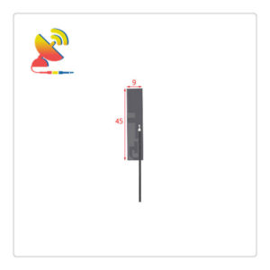
The Indoor PCB Antenna 3-8G UWB Antenna For Wireless Communications CTRF-ANTENNA-PCB-300800-4031-SMA is an indoor antenna PCB trace antenna with a 3000-8000MHz frequency SMA connector antenna supplied by C&T RF Antennas Inc for wireless transmission.
The Indoor antenna PCB Antenna UWB Antenna For Wireless Communications is manufactured by C&T RF Antennas Inc. We provide the extra-wide band antenna for the wireless communication industry.
C&T RF Antennas Inc provides internal & external antennas with antenna radio frequencies such as NFC, 169MHz, 230MHz, 315MHz, 433MHz, 868MHz, 915MHz, VHF&UHF, Lora, NB-IoT, ADS-B, GSM, GNSS, GPRS, 1.2 GHz, 1.4 GHz, 1.8 GHz, Wi-Fi 2.4 GHz, 5.8 GHz, Cellular 2G, 3G, 3.5 GHz, 4G LTE, GPS, 5G NR, 6G, etc.
C&T RF Antennas Inc. provides RF antennae with Omni & Directional antenna types such as Dipole Antennas, Whip Antennas, Marine Antennas, Router Antennas, MIMO Antennas, Combo Antennas, PCB Antennas, FPC Antennas, Spring Antennas, Magnetic Antennas, Sector Antennas, Yagi Antennas, and Accessories, etc, for IoT & M2M industries.
Contact us for more details on the UWB antennas.
3-8GHz UWB Antenna For Wireless Communications Specifications
3-8GHz UWB Antenna For Wireless Communications Electrical Specifications |
|
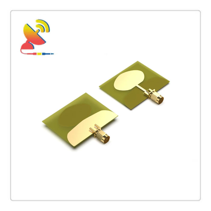
| RF Antenna Type | PCB Antenna |
| Model | CTRF-ANTENNA-PCB-300800-4031-SMA |
| Frequency | 3000-8000MHz |
| Gain | 6dBi/8dBi |
| VSWR | ≤3.0 |
| Impedance | 50 Ω |
| Polarization | Vertical/Linear |
| Connector | SMA Male |
| Lightning Protection | DC-Ground |
3-8GHz UWB Antenna For Wireless Communications Mechanical Specifications |
|
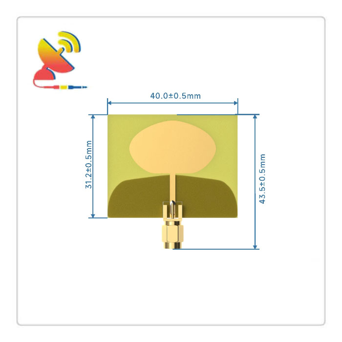
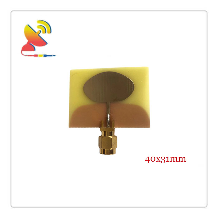
| PCB Board Dimension | 40*31mm |
| Weight | Approx. 10g |
| Material | PCB Board |
| Operation Temperature | -40˚C ~ +75˚C |
| Storage Temperature | -40˚C ~ +80˚C |
| Color | Yellow |
| Antenna Design | Dipole Antenna |
| Mounting | Screw |
| Safety, Emission, and other | RoHS Compliant |
More details of the 3-8GHz Indoor PCB Antenna UWB Antenna For Wireless Communications
What is UWB pulse shaping technology?
Any digital communication system must use signals that are well-matched to the channel to carry information. For linear modulation systems, the modulated signal can be uniformly expressed as:
s(t)=∑Ing(t -T)
Among them, In is a sequence of discrete data symbols carrying information; T is the duration of data symbols;
g(t) is the time-domain-shaped waveform. Many factors, such as the working frequency band, signal bandwidth, radiation spectrum density, out-of-band radiation, transmission performance, and implementation complexity of the communication system, all depend on the design of g(t).
For UWB communication systems, the bandwidth of the shaped signal g(t) must be greater than 500MHz, and the signal energy should be concentrated in the 3.1 GHz ~ 10.6 GHz frequency band.
Early UWB systems used nanosecond/sub-nanosecond level carrier-free Gaussian single-cycle pulses, and the signal spectrum was concentrated below 2 GHz.
The FCC’s redefinition of UWB and the allocation of spectrum resources put forward new requirements for signal shaping, and the signal shaping scheme must be adjusted.
In recent years, many effective methods have emerged, such as carrier modulation-based shaping technology, Hermit orthogonal pulse shaping, and ellipsoidal spherical wave (PSWF) orthogonal pulse shaping.
1. Gaussian one-cycle pulse
The Gaussian one-cycle pulse, that is, the derivatives of the Gaussian pulse, is the most representative non-carrier pulse. The pulse waveform of each order can be obtained by successively deriving the first derivative of a Gaussian.
As the order of the pulse signal increases, the number of zero-crossing points gradually increases, and the center frequency of the signal moves to high frequency, but the signal bandwidth does not change significantly, and the relative bandwidth gradually decreases.
Early UWB systems used 1st and 2nd order pulses, and the signal frequency component continued from DC to 2GHz. According to FCC’s new definition of UWB, sub-nanosecond pulses of order 4 or higher must be used to meet the radiation spectrum requirements.
2. Carrier modulation shaping technology
In principle, as long as the signal -10dB bandwidth is greater than 500MHz, UWB requirements can be met. Therefore, the traditional signal-shaping solutions used in carrier-based communication systems can be transplanted to UWB systems.
At this time, the ultra-wideband signal design is transformed into a low-pass pulse design, and the signal spectrum can be flexibly moved on the frequency axis through carrier modulation.
The shaped pulse with a carrier can be expressed as:
w(t)=p(t)cos(2πfct)(0≤t ≤Tp)
Among them, p(t) is the baseband pulse with duration Tp; FC is the carrier frequency, that is, the signal center frequency. If the frequency spectrum of the baseband pulse p(t) is P(f), the frequency spectrum of the final shaped pulse is:
It can be seen that the frequency spectrum of the shaped pulse depends on the baseband pulse p(t). As long as the -10dB bandwidth of p(t) is greater than 250 MHz, the UWB design requirements can be met. By adjusting the carrier frequency FC, the signal spectrum can be in the range of 3.1 GHz to 10.6 GHz.
Flexible movement within the enclosure. If combined with frequency hopping (FH) technology, a frequency hopping multiple access (FHMA) system can be easily formed. This pulse shaping technique is used in many IEEE 802.15.3a standard proposals.
Reviews
There are no reviews yet.