Description
What is Power Amplifier 100W PA used for?
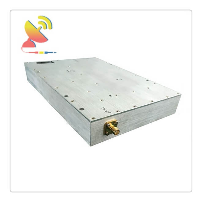
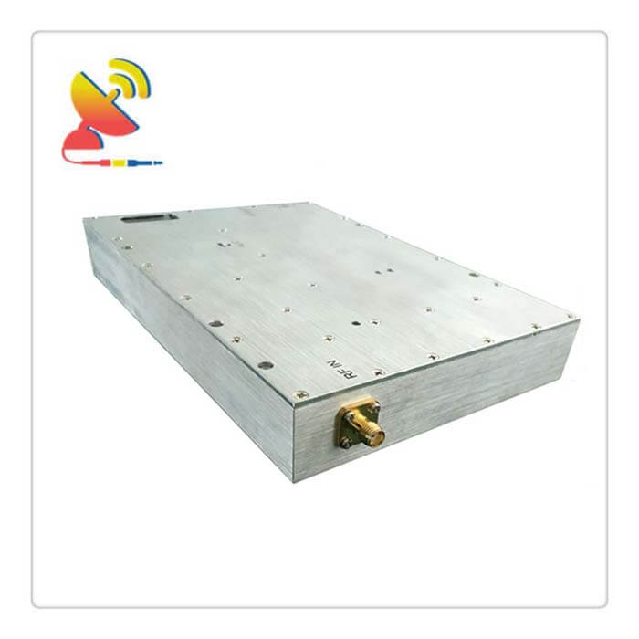
The Power Amplifier 100W 400-450MHz UHF Amplifier CTRF-ANTENNA-AMP-PA-0433-100W is a 433 MHz amplifier supplied by C&T RF Antennas Inc and is used for a variety of linear and non-linear modulation schemes, such as TV transmitters, digital radio, radio remote control, FSK and GFSK communication, walkie-talkies, and other systems.
Besides the Power Amplifier 100W UHF Amplifier, we also provide other watts and frequencies power amplifiers for your best choice.
Power Amplifier 100W 400-450MHz UHF Amplifier Is Supplied By C&T RF Antennas Inc. We provide RF products with RF antennas, Antenna Accessories, Amplifiers, And Repeaters.
C&T RF Antennas Inc provides internal & external antennas with antenna radio frequencies such as NFC, 169MHz, 230MHz, 315MHz, 433MHz, 868MHz, 915MHz, VHF&UHF, Lora, NB-IoT, ADS-B, GSM, GNSS, GPRS, 1.2 GHz, 1.4 GHz, 1.8 GHz, Wi-Fi 2.4 GHz, 5.8 GHz, Cellular 2G, 3G, 3.5 GHz, 4G LTE, GPS, 5G NR, 6G, etc.
C&T RF Antennas Inc. provides RF antennae with Omni & Directional antenna types such as Dipole Antennas, Whip Antennas, Marine Antennas, Router Antennas, MIMO Antennas, Combo Antennas, PCB Antennas, FPC Antennas, Spring Antennas, Magnetic Antennas, Sector Antennas, Yagi Antennas, and Accessories, etc, for IoT & M2M industries.
We Offer Power Amplifier 100W PA Pricing, Power Amplifier 100W PA datasheet & Datasheets For Power Amplifier 100W, and Power Amplifier Desing. Contact us now.
Power Amplifier 100W UHF Amplifier 400-450MHz Power Amplifier Technical Specifications:
| Model | CTRF-ANTENNA-AMP-PA-0433-100W |
| Frequency(MHz) | 400-450 |
| Input Power | ≤20dBm |
| Output Power(W) | 50±1(100W ) |
| ALC Range(dB) | ≥25 |
| In-Band ripple(dB) | ≤3 |
| Gain(dB) | 50 or Customized |
| Gain Adjustment Range(dB) | >31/1dB step or Customized |
| Gain Adjustment Linearity(dB) | ≤±1 |
| Gain Flatness(dB) | ±0.5(Max) |
| Impedance(ohm) | 50 |
| VSWR | ≤1.4:1 |
| Voltage(V) | DC+28 |
| Power Current | ≤6.5A |
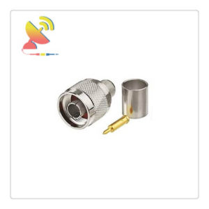
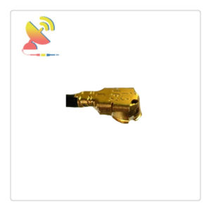
| RF Connector | SMA-50K or other Customized |
| Monitor interface | RS-485 or RS232 or other Customized |
| Monitoring communication protocols | Use the Manufacturer’s protocol or Customized |
| Working Temperature | -40~+65 degree |
| Storage Temperature | -55 to +85 degree |
| Operating Humidity | 0 to 90%, relative |
| Surface Color | Metal color conductive oxide and other color customized |
| weight | ≤1.2KG |
| Remark | Module with output short circuit or open circuit protection |
Power Amplifier 100W UHF Amplifier 400-450MHz Power Amplifier Monitoring Function Description:
| No. | Monitoring function | Description | |
| 1 | Query | PA ALARM | When an alarm amplifier failure |
| 2 | SWR ALARM | Amplifier output reflection is too large, VSWR exceeds3:1, an alarm is generated | |
| 3 | Over-temperature alarm | Module internal temperature exceeds85 ℃ generates an alarm and turns off the amplifier until the temperature returns tobelow65 ℃,re-open the amplifier | |
| 4 | Over-output power alarm | When the output power exceeds the nominal full power2dBisan alarm | |
| 5 | Input power detection | Accuracy of± 1dB | |
| 6 | Reverse power detection | Accuracy of± 1dB | |
| 7 | Output power detection | Detecting the actual output power amplifier, Accuracy of± 1dB | |
| 8 | Temperature detection | Detection module operating temperature, detection range: -25 ~ +90 ℃, Accuracy of± 3 ℃ | |
| 10 | SWR | Detecting amplifier output port VSWR range of 1.2~ 4.0 | |
| 11 | Query and set | PA attenuator Set and query | Set and query the value of ATT |
| 12 | PA switching query and set | Query and set the state open tube amplifier | |
RF Power Amplifiers for Wideband Modulations
RF Power Amplifiers for wideband modulations such as CDMA or WCDMA, which operate in the linear region, are not very efficient. Only a portion of the D.C. current is used to generate the RF power; a much larger portion turns into heat.
LDMOS and GaN (Gallium Nitride) devices are best suited for the output and driver stages because of higher gain, improved linearity, and very low on-resistance.
High gain reduces the number of stages needed in the amplifier to attain the same output power, compared to the old generation systems built with bipolar transistors.
In a multi-stage linear power amplifier, there are various factors that need to be considered for choosing the right transistor for each of the stages of the amplifier.
The pre-driver is biased Class-A for attaining consistent performance for minimal effect on the linearity of the device due to minor changes in bias supply.
Drain efficiency is not as much of a concern for the pre-driver as it is for the latter stages in the amplifier. The driver and the output stage for such a system are typically biased Class AB, for achieving the best tradeoff between linearity and efficiency of the amplifier.
The most common method used to determine the linearity of a transistor is to characterize the Intermodulation Distortion (IMD) measured with two tones spaced.
Typically, tone spacing up to 20 MHz should be used while tuning amplifiers for wideband modulation applications.
When transistors are used significantly backed off from their peak power levels, it is all the more necessary that the IMD characteristics of the transistor at lower output power levels be taken into account.
The profile of an IMD vs. Pout (drive-up) curve for a good transistor should have a large positive slope, even while attaining similar peak power capability, to get maximum Adjacent Channel Power Ratio (ACPR).
The transistor used in the driver stage has similar linearity requirements as the output stage. In terms of ACPR, it needs to be operated at an output power that gives a margin of at least 4 dB from the maximum allowed value for the output stage.
In addition, it needs to have an input bandwidth of about 2 to 2.5 times greater than the bandwidth of the modulating signal in order to maintain constant group delay and flat gain.
One of the major factors determining the performance of the high-power transistor in the wide modulation environment is the gain flatness. The transistor needs to have a flat gain across the band for its use in multiple-channel amplifiers.
A very flat gain response greatly simplifies the design of linearization scheme systems. The fast roll-off of gain at the edges of the band causes deterioration in the ACPR performance.
To attain the intrinsic device linearity, the 3 dB bandwidth of bias networks needs to be at least two times greater than the modulation bandwidth.
For attaining the best ACPR response, it is necessary to have an excellent decoupling network at the Drain of the transistor, down to very low modulation frequencies.
This can be achieved by using a high-quality shunt capacitor. This technique helps in achieving maximal gain flatness, which is very critical for wideband applications.
It is advisable to avoid ferrite components in the biasing network and to use a series resistor on the Gate bias network to prevent instability.
To achieve a flat gain response across the band, the traditional inductive feed should be avoided in both the Gate and Drain.
Instead, a quarter-wave line at the frequency of interest, properly decoupled with a chip capacitor, has been shown to provide a very flat gain across the entire bandwidth.
Reviews
There are no reviews yet.