Description
What is a 3dBi Antenna GSM SMA Rubber Duck Antenna?
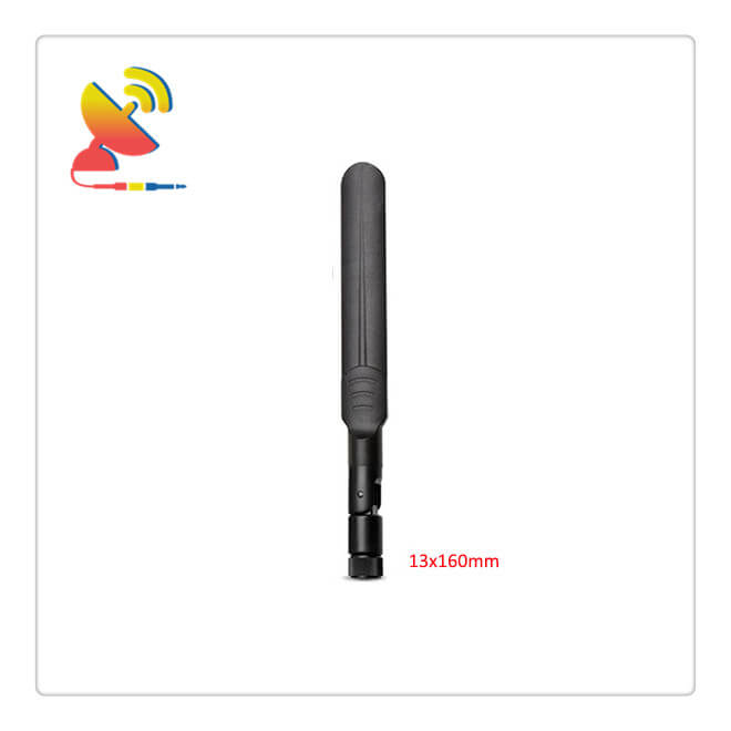
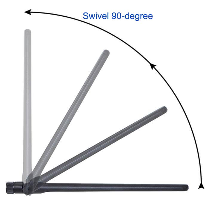
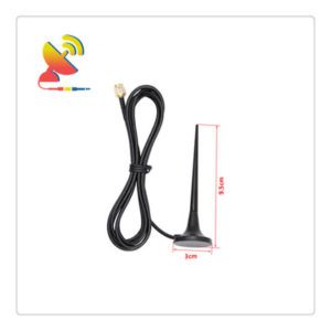
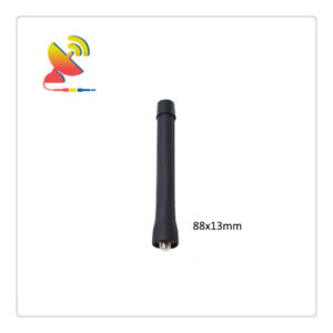
The GSM Antenna SMA antenna CTRF-ANTENNA-AP-8221-13158-SMA-B is a GSM dipole antenna with SMA male connector, black color rubber duck antenna radome, swivel 90-degree, can direct mount to network devices or magnetic base mount with antenna cable extension 3dBi GSM antenna manufactured by C&T RF Antennas Inc.
This Antenna GSM SMA Rubber Duck Antenna works for 2G, GPRS, 3G, GSM, and NB-IoT applications.
In this style, we have a WHITE color version GSM Omni Antenna for your choice.
For the same antenna radome, we have the 4G LTE antenna style for your choice too.
The Antenna GSM SMA Rubber duck antenna is manufactured by C&T RF Antennas Inc, the GSM antenna manufacturer in China.
C&T RF Antennas Inc provides RF antennas with other antenna radio frequencies such as 169MHz, 230MHz, 315MHz, 433MHz, 868MHz, 915MHz, Lora, VHF&UHF, NB-IoT, GSM, Wifi 2.4GHz, 5.8GHz, 2G 3G 4G LTE, GPS, 5G NR, UWB, etc.
C&T RF Antennas Inc provides the GSM antenna with many antenna types such as Dipole Antennas, Whip Antennas, Marine Antennas, Router Antennas, MIMO Antennas, PCB Antennas, FPC Antennas, Spring Antennas, etc, for IoT & M2M industries.
Contact us for more details on the Antenna GSM SMA Rubber Duck Antenna such as Antenna GSM SMA datasheet, Antenna GSM SMA pricing, and Antenna GSM SMA Rubber Duck Antenna inventory.
Or other GSM SMA antenna styles.
3dBi Antenna GSM SMA Rubber Duck Antenna Specifications
3dBi Antenna GSM SMA Rubber Duck Antenna Electrical Specifications |
|
| RF Antenna Type | Omni Antenna |
| Model | CTRF-ANTENNA-AP-8221-13158-SMA-B |
| Frequency Center | 824-960, 1710-2170MHz |
| Gain | 3dBi |
| VSWR | ≤2.0 |
| Impedance | 50 Ω |
| Polarization | Linear |
| Directional | Omnidirectional |
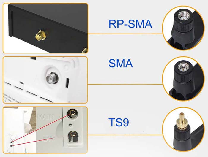
| Connector | SMA Male |
| Max Power | 50W |
| Lightning Protection | DC-Ground |
3dBi Antenna GSM SMA Rubber Duck Antenna Mechanical Specifications |
|
| Dimension | 13*158mm |
| Weight | Approx. 20g |
| Radome Material | Plastic ABS |
| Operation Temperature | -20˚C ~ +80˚C |
| Storage Temperature | -40˚C ~ +85˚C |
| Color | Black |
| Antenna Design | Dipole Array |
| Mounting | SMA Connector |
| SafetyEmission and other | RoHS Compliant |
| Applications | Public Safety/LMR/P25/TETRA, ISM/SCADA/Utilities, RFID, IoT/NB-IoT/LoRa/GPRS/GSM/2G/3G |
Omnidirectional Rubber Ducky Antenna Features

Rubber Duck Antenna Applications

How is the GSM operating frequency band allocated?
China’s land-based public cellular digital mobile communication network GSM communication system uses the 900 MHz bands.
890 ~ 915 (mobile station transmit, base station receive)
935 ~ 960 (base station to send, mobile station to receive)
The duplex interval is 45 MHz, the operating bandwidth is 25 MHz, and the carrier frequency interval is 200 kHz.
With the development of services, it can be extended downward as needed or transition to GSM 1800 in the 1.8 GHz band, i.e. 1800 MHz band.
1710 to 1785 (mobile station transmits, the base station receives)
1805~1880 (sent by the base station and received by the mobile station)
The duplex interval is 95 MHz, the operating bandwidth is 75 MHz, and the carrier frequency interval is 200 kHz.
What is the GSM channel spacing like?
The interval between two adjacent channels is 200 kHz. Each channel is divided into 8-time slots, i.e., 8 channels (full rate), using the Time Division Multiple Access (TDMA) method. Each channel occupies a bandwidth of 200 kHz / 8 = 25 kHz.
In the future, when GSM adopts half-rate voice coding, each channel can accommodate 16 half-rate channels.
What do the GSM multiple access schemes look like?
The GSM communication system uses multiple access techniques: a combination of frequency division multiple access (FDMA) and time division multiple access (TDMA), also coupled with frequency hopping techniques.
A basic concept of GSM transmission on the wireless path is that the unit of transmission is a sequence of about one hundred modulated bits, which is called a “burst pulse”. The pulses have priority in duration and also occupy a limited part of the radio spectrum.
They are sent within a time window and a frequency window, which we call a gap. Precisely, the center frequencies of the gaps are arranged at 200 kHz intervals in the system band (FDMA case), and they occur every 0.577 ms (more precisely, 15/26 ms) (TDMA case).
The time interval corresponding to the same gap is called a time slot, and its duration will be used as a time unit called BP (Burst Pulse Period).
Such a gap can be represented in the time/frequency diagram by a small rectangle 15/26ms long and 200KHz wide. Uniformly, we refer to the 200 kHz bandwidth specified in GSM as a frequency gap.

Reviews
There are no reviews yet.