Description
What is Spring Coil Antenna 433MHz Helical Antenna?
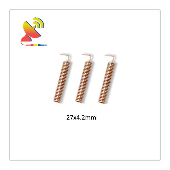
The Spring Coil Antenna 433MHz Helical Antenna Is An RF Receiver Antenna 433 Mhz Frequency Embedded Spring Antenna manufactured by C&T RF Antennas Inc.
The 433MHz Helical Antenna Comes With 2.5dBi Gain, 27×4.2mm Size.
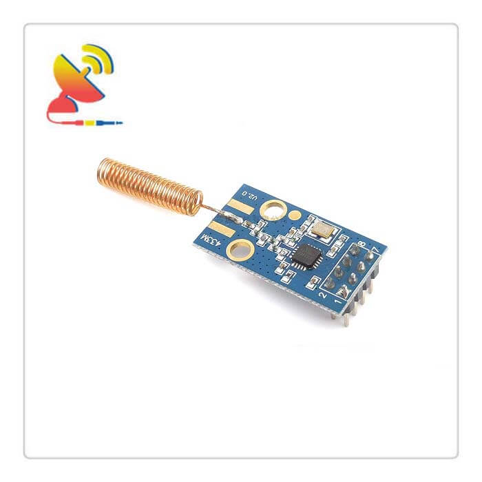
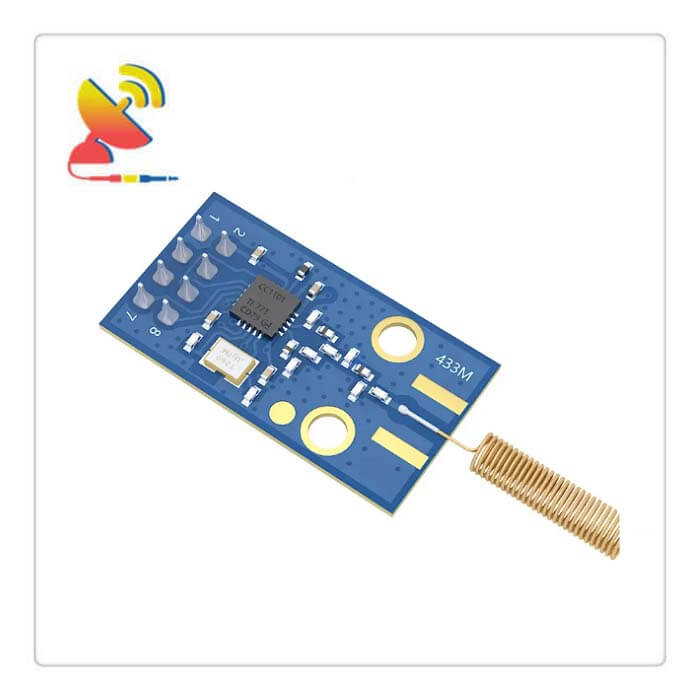
The Spring Coil Antenna 433MHz Helical Antenna is a dedicated antenna designed for wireless data transmission systems. The antenna has a good standing wave ratio, small size, smart structure, convenient installation, stable performance, and good anti-vibration and aging ability.
The 433MHz Helical Antennas are rigorously tested in the wireless data transmission system simulation environment by the network analyzer before leaving the factory.
C&T RF Antennas Inc provides internal & external antennas with antenna radio frequencies such as NFC, 169MHz, 230MHz, 315MHz, 433MHz, 868MHz, 915MHz, VHF&UHF, Lora, NB-IoT, ADS-B, GSM, GNSS, GPRS, 1.2 GHz, 1.4 GHz, 1.8 GHz, Wi-Fi 2.4 GHz, 5.8 GHz, Cellular 2G, 3G, 3.5 GHz, 4G LTE, GPS, 5G NR, 6G, etc.
C&T RF Antennas Inc. provides RF antennae with Omni & Directional antenna types such as Dipole Antennas, Whip Antennas, Marine Antennas, Router Antennas, MIMO Antennas, Combo Antennas, PCB Antennas, FPC Antennas, Spring Antennas, Magnetic Antennas, Sector Antennas, Yagi Antennas, and Accessories, etc, for IoT & M2M industries.
Contact us for the 433MHz Helical Antenna for more details such as 433MHz Helical Antenna datasheet, 433MHz Helical Antenna pricing, 433MHz Helical Antenna inventory, or other 433MHz Helical Antenna types.
Spring Coil Antenna 433MHz Helical Antenna Specifications:
433MHz Helical Antenna Electrical Specifications |
|
| RF Antenna Type | Embedded Spring Antenna |
| Model | CTRF-ANTENNA-SP-0433-2704 |
| Frequency | 433MHz |
| Gain | 2.5dBi |
| VSWR | ≤2.0 |
| Impedance | 50 Ω |
| Polarization | Vertical Polarization |
| Lightning Protection | DC-Ground |
433MHz Helical Antenna Mechanical Specifications |
|
| Dimension | 27*4.2mm |
| Weight | Approx. 3g |
| Material | Copper Wire |
| Operation Temperature | – 40 ˚C ~ + 65 ˚C |
| Storage Temperature | – 40 ˚C ~ + 70 ˚C |
| Finished Antenna Color | Copper |
| Antenna Design | Internal Antenna |
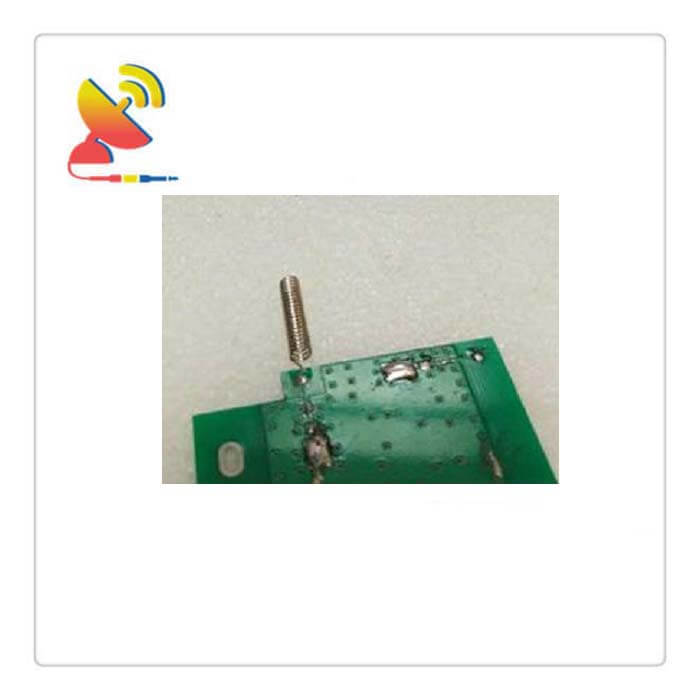
| Mounting | Connector/Soldered |
| SafetyEmission and other | RoHS Compliant |
| Applications | Public Safety/LMR/P25/TETRA, ISM/SCADA/Utilities, RFID, IoT/NB-IoT/LoRa, etc. |
Applications of Spring Coil Antenna 433MHz helical Antenna
How to make a 433MHz helical antenna design?
With the rapid development of wireless sensing technology, 433 MHz wireless communication equipment has been widely used in portable equipment, vehicle terminals, smart locks, and other fields.
As an important part of wireless communication equipment, the antenna is a key component that affects the overall performance of the communication system.
In this design, a 433 MHz miniaturized spiral printed antenna is designed based on a 1/4 wavelength monopole antenna. The simulation results show that the antenna occupies only 20×35 mm2 and the effective gain is -4.14 dB.
1. The structure design of the antenna
The spiral printed antenna designed in this paper uses a microstrip line to be wound on the upper and lower layers of the dielectric substrate to imitate the wiring form of the spiral antenna.
The wiring ends of the upper and lower layers of the spiral-printed antenna are connected by copper holes with a radius of 0.3 mm, which not only increases the effective length of the current path but also saves the space required for antenna wiring.
2. Research and optimization of antenna structure parameters
In order to obtain the optimal antenna structure size, HFSS is used to establish an antenna model, and the various structural parameters of the antenna are simulated and optimized.
2.1 The influence of antenna structure on antenna performance
(1) The influence of L on the antenna resonance frequency
Keep the other structural parameters of the antenna unchanged, scan the return loss of the antenna when L1=14 mm, L2=13 mm, and L3=12 mm with the help of the parameter scanning function of HFSS, and get the resonant frequencies of the antenna to be 628 MHz, 653 MHz and 684, respectively MHz.
Therefore, it can be concluded that as L increases, the resonant frequency gradually decreases, and vice versa.
(2) D’s influence on the antenna resonance frequency
Keep other structural parameters of the antenna unchanged, scan the return loss of the antenna when D1=2 mm, D2=1.8 mm, and D3=1.6 mm, and get the resonant frequencies of the antenna to be 644 MHz, 653 MHz, and 663 MHz, respectively.
Therefore, it can be concluded that as D increases, the resonant frequency gradually decreases, and vice versa.
(3) W influences the antenna resonance frequency
Keep other structural parameters unchanged, scan the return loss of the antenna when W1=0.8 mm, W2=0.9 mm, and W3=1 mm, and get the resonant frequencies of the antenna to be 653 MHz, 667 MHz, and 674 MHz, respectively.
Therefore, it can be concluded that as the antenna width W increases, the resonant frequency gradually increases, and vice versa.
2.2 The impedance matching of the antenna and the loading of the passive lumped original
The impedance matching between the antenna and the feeder will affect the resonant frequency of the antenna, and will directly affect the signal transmission efficiency between the antenna and the transceiver.
Inserting an impedance-matching network between the antenna and the feeder can reduce the loss caused by impedance mismatch.
Therefore, it is very important to match the impedance of the antenna.
3. Analysis of antenna simulation results
Use HFSS to run the antenna model with an optimized structure and analyze the simulation results.
3.1 Return loss analysis
3.2 Gain analysis
Antenna gain is one of the most important indicators of an antenna. The gain value of the antenna in each direction of the E plane and the H plane is the main basis for judging the antenna gain characteristics.
Through research and analysis, a 433 MHz miniaturized spiral printed antenna is designed.
The antenna design incorporates the structural characteristics of the traditional external helical antenna and the monopole snake-shaped printed antenna. The microstrip line is used to imitate the wiring form of the helical antenna on the dielectric substrate, which reduces the structural size of the antenna.
In addition, the loading of passive lumped elements ensures the miniaturization of the antenna, so that the antenna does not need to extend the physical length to reduce the resonance frequency. The final simulation test results show that the performance of the antenna meets the expected indicators.
Besides the Ground Plane Antenna 433MHz Helical Antenna, C&T RF Antennas Inc also supplies the spring antenna coil helical antenna with 315 Mhz, 433 Mhz, 868 Mhz, 915 Mhz, Wifi, GSM, etc.
Ground Plane Antenna 433MHz Helical Antenna Video

Reviews
There are no reviews yet.