8 Steps Of 5G Array Antenna Design

After the read, you will learn the 8 Steps Of 5G Array Antenna Design, here we go!

5G, the fifth-generation wireless communication technology, is an indisputable fact as a global hot topic. As many experts have stated, this technology reduces latency, accelerates data communications, and leads to the explosive growth of connected devices.

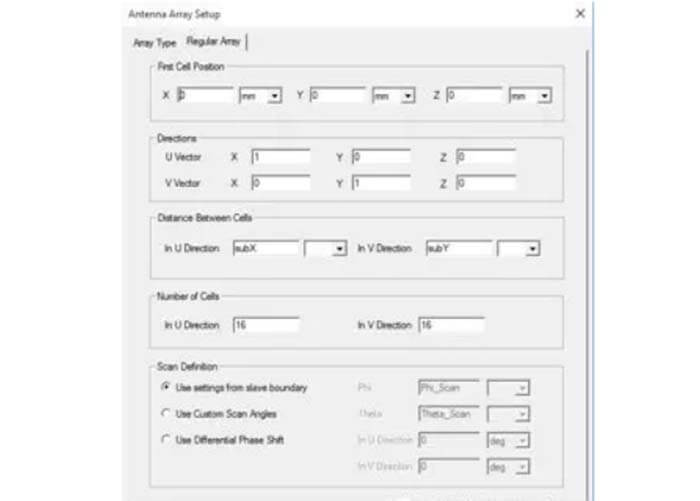
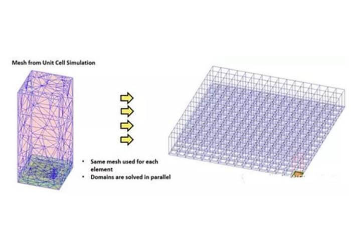
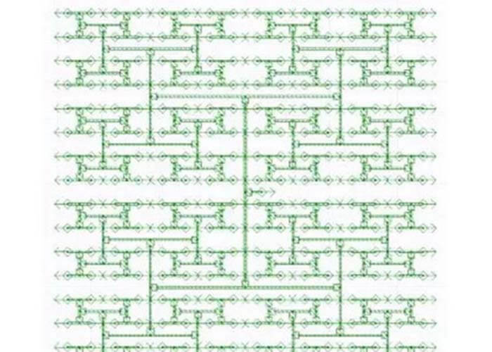
As the bandwidth requirements of 5G networks grow, the antenna array will need to be completely redesigned. From units to arrays, feeder networks, complete model validation, and application scenario evaluation, complete and sophisticated simulation and optimization designs are required.

The greater bandwidth requirements of 5G networks require that 5G antenna arrays must be completely redesigned. From unit to array, to feeder network, to full model verification and application scenario evaluation, complete and refined simulation and optimization design are required.

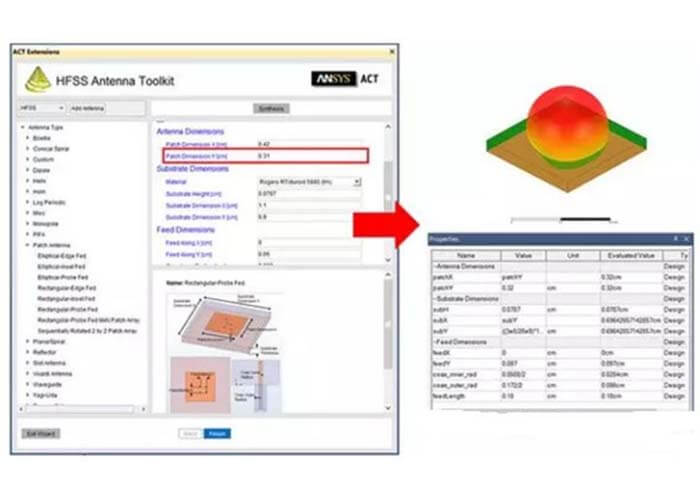
With the help of HFSS, we can easily complete the design and comprehensive verification of your 5G antenna array in just 8 steps. The more convenient HFSS also helps engineers optimize various antenna performance indicators, including:

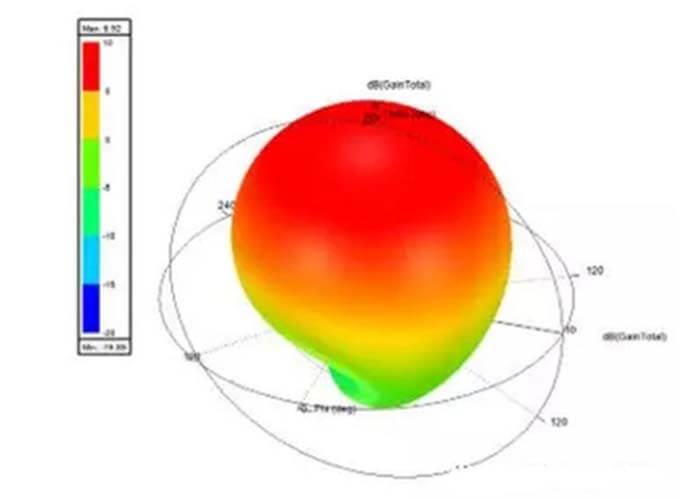
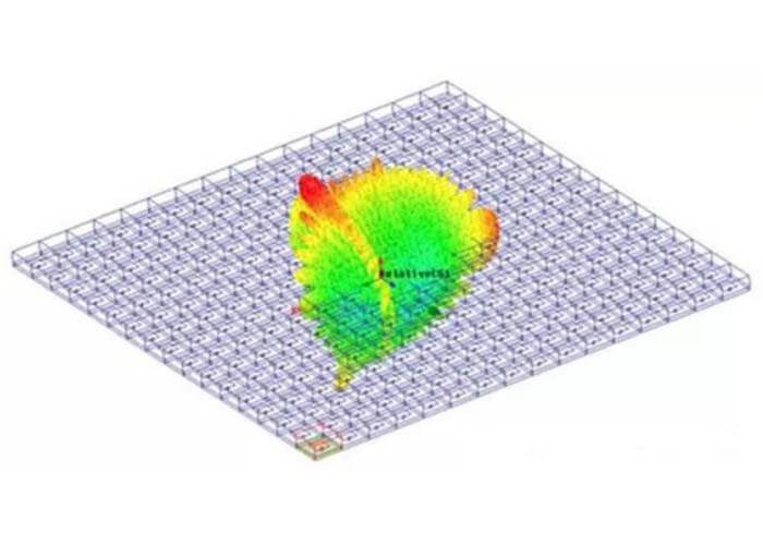
Gain: The direction of the strongest signal emission.

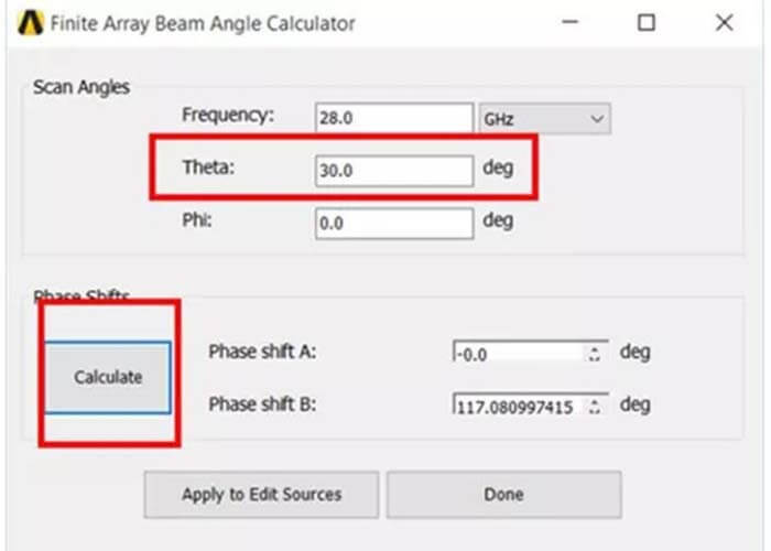
Beam control: You can control the signal emission in a specific direction.

Return loss: Return energy reflected from the antenna.

Sidelobe level: Unwanted signal emission direction.

At the end of the design process, the resulting array antenna has higher focus gain, lower reflection attenuation, and sidelobe levels, and more controllable orientation.

8 steps of 5G array antenna design - C&T RF Antennas Inc

5G Array Antenna Design Step 1: Find the antenna unit template from the HFSS Antenna Toolbox (ATK)

The first step in designing a 5G antenna array is to find a suitable antenna unit template via the HFSS Antenna Toolbox (ATK). The antenna element defines the same component that is ultimately replicated in a series of antennas (antenna array).

C&T RF Antennas Inc-1 Find the antenna unit template from the HFSS Antenna Toolbox (ATK)

First, select the antenna type from the Antenna Toolbox (ATK) library, then enter the operating frequency and antenna board attributes.

After a few seconds, the Antenna Toolbox (ATK) will generate the initial geometry of the antenna element. The HFSS can then also calculate index characteristics such as antenna unit gain and return loss.

5G Array Antenna Design Step 2: Replace the antenna unit with an antenna array

C&T RF Antennas Inc-2 Replace the antenna unit with an antenna array

The antenna unit allows engineers to replace it with a periodic array. Replacing the unit with a series of duplicated designs can help increase the gain.

In the first step, the antenna unit is self-assessed. You can now repeat the evaluation process using the periodic elements of the infinite antenna array.

It is easy to see that the distance of the other antennas in the array affects the gain, return loss, sidelobe echo, and beam steering characteristics. Of course, these characteristics can also be optimized by adjusting the antenna position.

After choosing the optimal array orientation, you can change an infinite array to an ideal finite array by defining the array coefficients.

In this example, a 16×16 square antenna array is simulated.

5G Array Antenna Design Step 3: Design a finite antenna array using the domain decomposition method

Since the design of the antenna array does not require an ideal model, the next step is to build a realistic simulation to better see how each antenna element interacts with the edges of the array. Is to understand.

C&T RF Antennas Inc-3 Design a finite antenna array using the domain decomposition method

The simulation method is completed by adopting the area division (DDM) method. The domain decomposition method copies a mesh of a single cell and applies it to the geometry defined in the second step. The boundaries of each grid are stitched overlapping the adjacent grids to evaluate the coupling of adjacent array units.

High-performance computing platforms and domain decomposition methods can be used to distribute the computational load on each antenna unit grid and solve in parallel using multiple processor cores, accelerating the solution.

Once the grid is created, HFSS can be used to evaluate and optimize antenna gain, reflection attenuation, sidelobe levels, and beam control. The accuracy is better than the method in step 2.

5G Array Antenna Design Step 4: Calculate the beam angle of the finite antenna array

If you can’t control the direction in which the signal is transmitted, the 5G antenna becomes meaningless. Here you can use the HFSS Limited Array Beam Angle Calculator to calculate the phase shift required to direct the beam in a particular direction based on the signal frequency and sweep/phase angle. These angles are used to identify the array antenna in the spherical coordinate system.

C&T RF Antennas Inc-4 Calculate the beam angle of the finite antenna array

Based on the grid created in step 3, the computer can determine the relationship between the antennas in the array and the specific scan angle of the beam.

5G Array Antenna Design Step 5: Design an antenna array feeding network

C&T RF Antennas Inc-5 Design an antenna array feeding network

The next step is to design the array feeder network.

First, determine the phase relationship and amplitude of the target, then design and iterate over the feed network with HFSS until the target is reached.

When designing the power supply circuit of an array repeatedly, it is possible to estimate how each iteration affects the amplitude-phase relationship.

After you have finished wiring each array and optimized your settings, you can start connecting all your designs in a complete simulation project.

5G Array Antenna Design Step 6: Connect all antenna array models in a simulation design

You can now route the finite element model created in step 3 based on the beam angle calculation in step 4 and the feed network in step 5.

In addition, phase shifters and control signals can be added. The phase shifter can be selected from the component library according to the phase angle calculated in step 4.

You can then perform linear network analysis (LNA) to evaluate the reflection attenuation index for this nearly completed simulation project.

5G Array Antenna Design Step 7: Push the antenna array excitation combination to HFSS

Now we need to push the excitation result from LNA to HFSS. Mismatch losses from the feed network are passed to the HFSS in the form of amplitude and phase values ​​and the results are plotted as a system gain map.

C&T RF Antennas Inc-7 Push the antenna array excitation combination to HFSS

Gain can more accurately reflect the radiation performance of the antenna in all directions.

5G Array Antenna Design Step 8: Test and evaluate the actual performance of the antenna in a real-world environment

The final step is to evaluate the design performance of the antenna in the environment in which it is used [YX1].

This process involves large-scale scenes and platforms, allowing HFSS ray tracing (SBR) technology to be used for system-level research. This study can calculate the ability of antennas to send and receive signals in large environments such as urban areas and other environments.

Facebook
Twitter
LinkedIn
Pinterest

Leave a Reply