In LPWAN, in the comparison of LoRa and Bluetooth, Zigbee, wifi, and other transmission schemes, a key factor in choosing LoRa is the long transmission distance of LoRa. The Lora antenna design is very important.
With the unique and superior transmission performance of LoRa technology, the group using LoRa technology is growing explosively. As a large part of the group is the first contact with LoRa and other radio frequency technologies, in the process of making products, they usually encounter tricky radio frequencies. Lora antenna circuit design issues, in fact, as long as you master a few major points, you can basically play the best performance of LoRa.
Point 1, matching circuit design
When designing the schematic diagram, a π-type matching circuit needs to be reserved between the antenna connector and the antenna pin of the module. The impedance of the antenna is affected by factors such as the floor of the circuit board, the housing, and the installation angle. This π-type matching circuit is reserved for correcting it to 50 ohms when the antenna seriously deviates from 50 ohms.
By default, the antenna impedance is relatively close to 50 ohms. In the figure below, C17 and C18 do not need to be soldered; and L2 uses 220pF capacitors, or 1nH inductance, or 0-ohm resistance, all three are acceptable. When encountering special circumstances, such as the inside of the antenna installation mold, the small size of the antenna, or the need to strengthen the suppression of high-order harmonics, these three matching components need to be matched and adjusted.
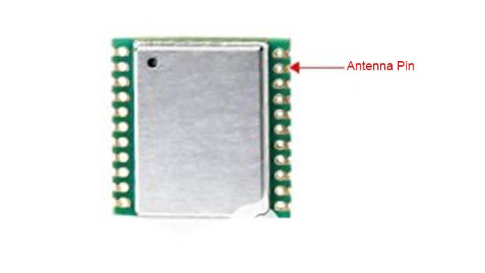
Figure 1 Reserved matching circuit for LoRa module application
In theory, no matter the antenna impedance is at any value, it can be matched to 50 ohms through a π-type matching circuit. However, in fact, inductors and capacitors have internal resistance. This internal resistance will absorb energy. If the antenna impedance is too small (a few ohms) or large (thousands of ohms), it will be meaningless to match it to 50 ohms through a matching circuit. The reason is that most of the energy has been consumed on the internal resistance of the matching element.
Point 2, microstrip line routing rules
The microstrip line mentioned here refers to the PCB trace from the antenna pin of the LoRa module to the antenna connector. The following figure is an example of the microstrip line on the evaluation board of the LoRa module. Since the internal impedance of the module and the antenna impedance are designed with the standard of 50 ohms, when the characteristic impedance of the microstrip line is also 50 ohms, the three are best matched.
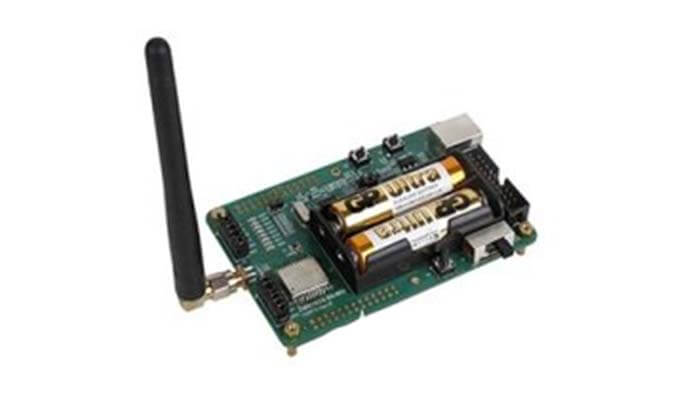
Figure 2 LoRa module hole antenna interface
In order to obtain a microstrip line of about 50 ohms, on the one hand, the impedance processing requirements can be raised to the PCB (antenna) manufacturer, and the capable PCB antenna manufacturer can control the trace impedance through the line width according to the board parameters; on the other hand, the board can be obtained from the PCB antenna manufacturer After the parameters (mainly the dielectric constant), the line width is calculated by the software, so as to control the impedance within the range we expect.
According to experience, if the FR4 board (dielectric constant between 4.2 and 4.6) is used when the line width is 2.2 times the distance from the microstrip line to the reference layer, the characteristic impedance is closer to 50 ohms. For example, in the case of double-sided boards, when the board thickness is 0.8mm, the line width is 1.7mm.
But it must be noted that the ground under the microstrip line must be complete, and the distance between the microstrip line and the copper paving is set according to the calculation results of the impedance calculation software. The ground pads on both sides of the module antenna pins must be well-grounded.
Point 3, PCB floor requirements
We have encountered many situations like this, users use our module on the product, the product program uses the same configuration parameters as our evaluation board, and uses the antenna on our evaluation board, but the communication effect is significantly better than our evaluation board. It’s much worse.
There are three key parameters related to communication distance: transmitting power, receiving sensitivity, and antenna. The first two parameters were tested when our module was manufactured. Unqualified products are disposed of as scrap, while the antenna is due to the user’s design being different. The distance that affects the communication is mainly the antenna parameter, and the other two parameters will hardly change greatly due to the user’s motherboard.
The electromagnetic wave with a frequency of 433MHz has a wavelength of 63CM. If a standard half-wave dipole antenna is designed, this antenna will be at least half the wavelength, that is, 31.5CM. In practical applications, most products do not reserve such a large space for antenna design, so spring antennas are commonly used.
When using this spring antenna, the antenna is connected to a different motherboard, and its performance parameters are different. This is because in this type of antenna, the spring is only part of the entire antenna, and the other part is the ground on the circuit board, so you must pay attention to the circuit when laying the ground.
The general principle is as below showing.
First, make the antenna as vertical as possible for the circuit board to install,
The second is to make the copper block on the ground as large and continuous as possible, and it is also feasible to rely on dense vias to make the ground on both sides continuous.
Point 4, antenna installation specifications
After all the hardware parameters are adjusted, the installation of the antenna is also a key step. The antenna radiation is directional, and not equal energy is radiated in every direction. Just like when we speak, the sound heard in some directions is strong, and in some directions is weak. When installing the antenna, you need to align the direction of the antenna with the strongest radiation to the receiving antenna, so that the receiving antenna can obtain the strongest received signal. To do this, you must first know the radiation direction of the antenna.
If there is a professional antenna test laboratory in an anechoic chamber, directly use the anechoic chamber of the professional antenna test laboratory to test the radiation direction of the antenna and get the best location for the antenna installation.
In the absence of a professional antenna test laboratory such as a darkroom, how to test the antenna’s radiation direction? After finalizing the product, we can let it continuously send data, and use a spectrum analyzer to test the signal strength at a certain distance from the product, rotate the tested product, and record the signal strength in all directions, so that the antenna radiation of the product can be mapped General direction map.
How to place the LoRa antenna?
Place the antenna as far away as possible from the ground. Don’t touch the antenna with your hands during testing. The antenna is more than 2m away from the ground and the human body is more than 2m away from the antenna.
The antenna should not be close to large metal objects, and should not be placed near the river, so as to minimize obstacles between the antennas
The antennas should be placed upright, not flat on the ground, or skewed, and try to keep the antennas of the two communication parties on a level surface.
The antenna is a key part of the communication device and the sensitivity of the device is the main problem in LoRa technology.
Different ISM/Lora frequency bands need to be matched with different antennas. In the 868MHz frequency band, the length of the ɑλ/4 antenna is 8.2cm. Therefore, depending on the product, this must be taken into account in the mechanical design, so as to place the antenna correctly to avoid closed interference with the product itself.
There are 3 typical Lora antenna design architectures
This solution is the simplest because a dedicated antenna is very suitable for achieving the best results in terms of transmission and sensitivity. However, this solution is the most expensive.
This design is a simple trace on the circuit, but parameters such as the width and thickness of the copper wire must be considered in the antenna design process.
3. Simple quarter-waveguide line antenna
A simple quarter-waveguide line antenna (λ/4 length) may be the simplest way to implement it. The main challenge of this architecture is to ensure the repeatability of its products and provide the correct antenna length on each product.
This design must also have the correct mechanical parts to properly keep the wires inside the product to ensure consistent RF performance for all manufactured products.
How to choose the antenna of the LoRa module device?
Common antennas include PCB antennas, FPC antennas, spring antennas, rubber duck antennas, fiberglass antennas, and sucker cap magnetic mount antennas. According to the power and frequency of the LoRa module, Lora gateway, and LoraWan node, different antenna matching can be selected.
100mW LoRa modules can choose spring antennas, modules above 500mW can choose rubber duck antennas, modules above 2W can choose suction cup magnetic mount antennas, and outdoor Lora applications can choose fiberglass antennas.
Lora antennas generally have a range of frequency bands that they support. If used outside the frequency band, the performance of the antenna will decrease to a certain extent. Therefore, when using it, try to make the device work in the frequency band supported by the antenna to achieve the best transmission effect.
Generally speaking, the gain of a fiberglass antenna is higher than that of a sucker antenna, a rubber antenna, and a spring antenna.
In a communication system, the strength of the gain will interfere with the antenna’s ability to radiate or receive wireless signals; under the same conditions, the higher the gain, the longer the wireless signal propagation distance. Therefore, in order to increase the communication distance of the wireless module, it is also a good way to choose a high-gain antenna.
C&T RF Antennas Inc antenna manufacturer conducted in-depth tests and concluded that the following factors should be paid attention to when LoRa antennas are used in equipment.
- The Lora node/Lora gateway (module or device) needs to be equipped with an antenna even if it is very close to the receiving end (module or gateway), otherwise, the data may not be received;
- Each link of the antenna may cause signal attenuation, including the antenna’s feeder line, U.FL to SMA connector transfer line, the length of the suction cup antenna line, etc., especially when the line length is long, it is necessary to fully consider the attenuation effect of the wire on the signal;
- The signal coverage of LoRa is not linear coverage at a long distance. Some areas will have blind areas due to factors such as construction and terrain, which need to be tested.
Finally, some core data for the selection of antennas are explained. Antennas are divided into omnidirectional antennas, directional antennas (with energy orientation and convergence functions, coverage 180 degrees, 120 degrees, 90 degrees coverage), panel antennas (wave velocity Angles of 30 degrees, 15 degrees), the current LoRa antennas are basically omnidirectional antennas.
There are many core parameters of antennas, but many parameters require professional equipment, even darkrooms to measure. When selecting a model, we mainly focus on several core parameters, the first of which is the gain of the antenna. (The gain parameters of the antenna are dBd and dBi, dBi is the gain relative to the point source antenna, and the radiation in all directions is uniform. The LoRa antennas on the market are basically marked with dBi).
Under the same other conditions, the higher the gain, the longer the radio wave propagation distance.
Secondly, it is the standing wave ratio. The closer the standing wave ratio is to 1, the better the antenna effect and the higher the efficiency.
The third is the center frequency, which must be consistent with the frequency selected by the module.
Therefore, to achieve the best transmission distance of LoRa, after the equipment is finalized, it is best to find a professional antenna manufacturer for antenna matching, especially the built-in antenna. A well-matched antenna has an immediate effect on the transmission distance.
C&T RF Antennas Inc provides a series of Lora antennas with the 2dBi Lora antenna, 2.5dBi Lora antenna, 3dBi Lora antenna rubber duck antennas; 3dBi Lora Antenna, 4dBi Lora Antenna, 5dBi Lora Antenna, 5.8dBi Lora antenna, 6dBi Lora Antenna, 8dBi Lora Antenna , 9dBi Lora Antenna, 10dBi Lora Antenna, 11dBi Lora Antenna, 12dBi Lora Antenna, 15dBi Lora Antenna, 20dBi Lora antenna fiberglass antennas, etc. We also provide internal & external Lora antenna design, contact us for more Lora antenna details.
Besides the 4 Points Of LoRa Antenna Design article, you may also be interested in the below articles.
What is the difference between WIFI and WLAN?
Summary of 41 Basic Knowledge of LTE
What Is The 5G Network Slicing?