Why 4G Smartphone Antenna Design is so impartant?
In mobile data devices, the antenna is the only component that touches the network, and optimizing antenna performance becomes more and more important. However, the challenges of the 4G antenna design in smartphones and tablet computers are very difficult. Although there are many possible solutions to these challenges, each has potential performance trade-offs.
4G Smartphone Antenna Design Challenges
There are many factors that affect the antenna performance of handheld mobile communication devices.
Although these factors are related, they can generally be divided into three categories, antenna size, mutual coupling between multiple antennas, and equipment usage models.
Antenna size depends on three factors, working bandwidth, working frequency, and radiation efficiency.
Today’s bandwidth requirements are getting higher and higher, and its driving force comes from the US FCC frequency allocation and global operator roaming agreements; different regions use different frequency bands. Bandwidth and antenna size are directly related, and efficiency and antenna size are directly related, which means that larger size antennas can provide greater bandwidth and higher efficiency.
In addition to bandwidth, the antenna size also depends on the operating frequency.
In North America, operators Verizon Wireless and AT&T Mobility chose to promote LTE products that work in the 700MHz frequency band, which was part of the FCC UHF-TV redistribution frequency band a few years ago.
These new frequency bands (17,704-746MHz and 13,746-786MHz) are lower than the traditional cellular frequency bands (5,824-894MHz) used in North America. This change is huge, because the lower the frequency, the longer the wavelength, which requires a longer antenna to keep the radiation efficiency constant.
In order to ensure radiation efficiency, the antenna size must be larger. However, equipment system designers also need to add larger displays and more functions, so the available antenna length and overall volume are greatly limited, thereby reducing antenna bandwidth and efficiency.
The updated high-speed wireless protocol for mutual coupling between antennas requires the use of MIMO (Multiple Input Multiple Output) antennas. MIMO requires multiple antennas (usually two) to work at the same frequency at the same time.
Therefore, multiple antennas need to be placed on the phone equipment, and these antennas must work at the same time and cannot affect each other. When two or more antennas are placed very close together, a phenomenon called mutual coupling occurs.
For example, two antennas are placed next to each other on the mobile platform. Part of the energy radiated from antenna 1 will be intercepted by antenna 2, and the intercepted energy will be lost in the terminal of antenna 2 and cannot be used. This can be represented by the loss of system power-added efficiency (PAE).
According to the principle of interchangeability, this effect is the same in sending and receiving modes. The coupling amplitude is inversely proportional to the separation distance of the antenna. For mobile phone implementation, the distance between antennas operating in the same frequency band in MIMO and diversity applications can be 1/10 wavelength or less.
For example, the free-space wavelength at 750MHz is 400mm. When the interval is very small, such as much less than one wavelength, the degree of coupling will be high. The energy coupled between antennas is useless and will only reduce data throughput and battery life.
Compared with traditional mobile phones, the use models of smartphones and tablets have changed greatly. In addition to normal operation, these devices must meet the electromagnetic energy absorption ratio (SAR) and hearing aid compatibility (HAC) regulations.
Another aspect of the usage model is the type of content consumed. Video-intensive mobile applications such as massively multiplayer online role-playing games (MMORPG) and real-time video data streaming continue to drive data usage soaring.
These similar applications are driving manufacturers to produce larger, higher-resolution displays. The increase in data usage is also quietly changing the way consumers hold these devices. For example, for a game application, the user must hold the device with both hands, while other applications may not need to hold the device.
Increasingly larger display screens and changes in the user’s gripping methods make it increasingly difficult to find a good location for the antenna radiation unit that is not blocked by the display screen or the user’s palm.
In addition to these constraints, equipment manufacturers hope that product series have fewer SKUs (smallest stock-keeping units), and the development of a platform that can work anywhere in the world is the development trend of such products.
4G Smartphone Antenna Design Solution
In order to be universal, smartphones or tablets must be able to work under various frequency bands and protocols. Of course, it is not required to work in all frequency bands and protocols at the same time, so an antenna system that can be adjusted to the target operating frequency band can be developed.
This state-tuned antenna can be called a smart antenna or an adaptive antenna. Its basic principle is to limit the instantaneous operating frequency to one or two narrowband frequency bands of interest to meet the protocol requirements of a specific area. In this way, the requirements for broadband operation are reduced, allowing the antenna to be installed in a more compact space without sacrificing radiation efficiency.
There are two basic methods for antenna tuning, feed point matching, and aperture tuning. However, there are many factors that affect the implementation decisions of these methods, and there is currently no single solution that can be suitable for every application.
Feed point matching can be used in many antenna implementations, whether tunable or non-tunable. The main function of the matching circuit is to match the antenna terminal impedance with the impedance of the rest of the radio system (usually 50Ω) under a wide range of working conditions.
A typical tunable matching implementation uses parallel or series variable capacitors as part of the impedance matching circuit. Adjusting the capacitance of the capacitor can change the resonant frequency of the target circuit.
To compress and tune the range according to the required antenna size, a larger range of capacity changes is generally required to achieve frequency shift, so multiple tuning elements and/or a wide range of tuning values are usually required. Figure 1 shows the antenna feed point matching circuit using variable elements.
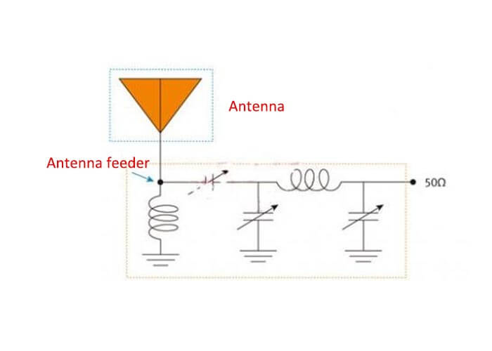
Figure 1 Fixed broadband antenna with variable impedance matching circuit of 4G Smartphone Antenna Design Solution
Aperture tuning is achieved by changing the resonant structure of the radiating element. A typical implementation is to use a simple switch to select different load components on the antenna structure. Switching load components affects the electrical length of the antenna, thereby changing the resonance frequency. Figure 2 is an AC circuit model of a variable state, aperture tuned antenna using a fixed impedance matching circuit.
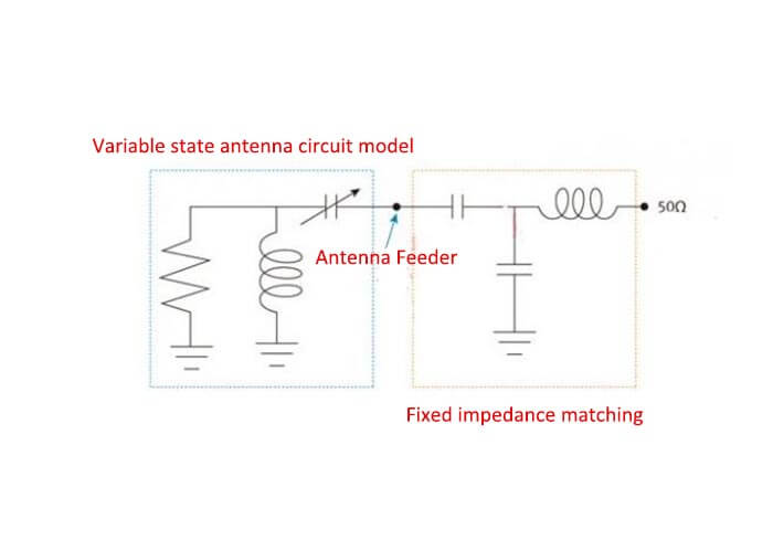
Figure 2 Variable state antenna with a fixed feed point matching circuit of 4G Smartphone Antenna Design Solution
Regardless of whether the feed point matching or aperture tuning method is used, if the antenna is used for both transmitting and receiving, then the tuning device must be able to withstand the maximum transmit power and maintain good performance characteristics.
Case Description
The following example illustrates the benefits of the tuning method in reducing the size of the antenna. Here we use a 3D electromagnetic modeling program to analyze two different antenna configurations: one is broadband design; the other is in the same frequency range tuned but uses a narrowband design with 4 tuning states.
Figure 3a shows a 60x8mm 7-band antenna configuration and the relative radiation efficiency in the lower three-band spectrum from 700MHz to 960MHz. Figure 3b shows a similar but smaller antenna configuration (32x8mm). It can be seen from the figure that the use of a 4-state tuning circuit can produce almost the same efficiency as a larger broadband antenna, and overall frequency coverage.
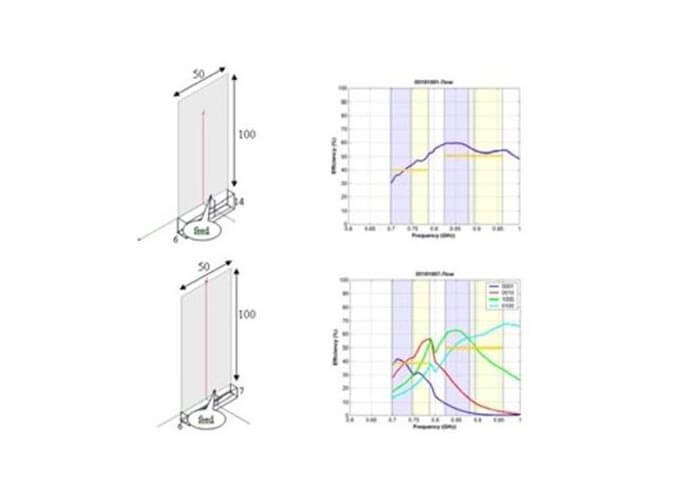
Figure 3 In the 700MHz to 960MHz range of 4G Smartphone Antenna Design Solution
- a) Multi-band antenna
- b) Comparison of the volume and radiation efficiency of the tuning antenna (antenna size unit: mm).
It can be clearly seen from the example in Figure 3 that by tuning the antenna to a certain state, each state supports a specific set of frequency bands, the physical volume of the antenna can be halved.
When the antenna is working, if you want to change the working frequency band, you only need to change the state. But the time required for this change must be consistent with the requirements of other functions in the radio system. The typical requirement is 10ms to 20ms or less.
The mutual coupling effect between adjacent antennas working at the same frequency at the same time will produce a mutual coupling effect, which can be mitigated by isolation technology. The most common technique is to physically separate the antennas from each other.
As the separation distance increases, the mutual coupling effect will decrease. However, for handheld devices, it is difficult to provide sufficient spacing to reduce the mutual coupling effect. In this case, system designers need to use other different antenna solutions to achieve the performance indicators required by the specification.
There is also a feasible solution, using the Isolated Mode Antenna Technology (iMAT) provided by SkyCross to generate two different modes from the same antenna structure.
The iMAT antenna structure is placed at one end of the mobile phone; the two feed points operate with different radiation patterns. These two feed points are isolated from each other, and there will be no loss caused by mutual coupling, so the efficiency of each mode is very high.
In addition, the radiation patterns are different, so a lower correlation coefficient is produced. Figure 4 describes the implementation principle of the iMAT antenna. From the figure, you can see the isolation between two feed points on the same antenna structure.
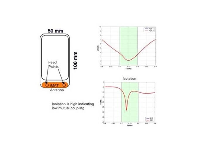
Figure 4 Principle of iMAT antenna realization of 4G Smartphone Antenna Design Solution
Use Model
In order to alleviate the influence of various usage models, it is necessary to combine the two methods of state tuning and mode isolation. Mode isolation allows a single antenna structure with multiple feed points to perform the function of multiple MIMO antennas;
While state tuning allows this structure to be very small, but still able to work very efficiently in a wide frequency range. Figure 5 shows the average measurement efficiency of the variable-state iMAT antenna structure covering multiple frequency bands with 6 tuning states.
The iMAT structure can work in balanced or unbalanced gain configurations and compared with traditional antenna design techniques, it can provide higher performance in a smaller package.
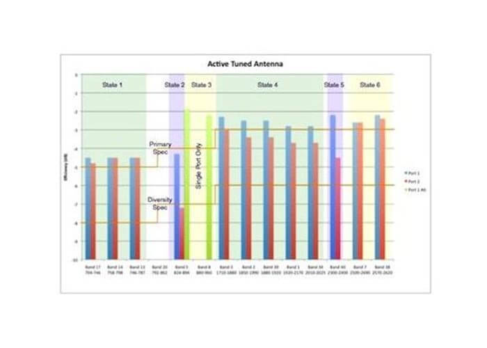
Figure 5 Covers all 3G 4G applications and has a state-tuned iMAT structure with two MIMO antenna ports
For complex smartphones and tablet devices, to achieve an efficient antenna system, huge challenges must be overcome. Emerging LTE and other 4G networks cover different frequency bands from 700MHz to 2700MHz. These new frequencies will be added to the traditional 3G frequency band to meet global mobile roaming and compatibility requirements.
Advanced wireless networks use MIMO in user equipment to increase data throughput. In addition, data-intensive applications such as online gaming and video streaming are giving rise to larger displays and a wide variety of usage models.
This also brings more problems to system designers, such as finding enough space on the device to implement a multi-band multi-antenna system. Fortunately, advanced antenna design technologies such as state tuning and iMAT can help designers calmly cope with the above-mentioned challenges, flexibly implement fashionable and feature-rich mobile devices, and provide true 4G network performance.
We are here to help you with your 4G smartphone antenna design.
Besides the 4G Smartphone Antenna Design Solution article, you may also be interested in the below articles.
What is the difference between WIFI and WLAN?
Summary of 41 Basic Knowledge of LTE
What Is The 5G Network Slicing?