The Yagi Antenna design is one of the most brilliant antenna designs. How to make a 433MHz Yagi antenna design for a long-range? Is it easy to DIY a Yagi antenna?
What is Yagi antenna?
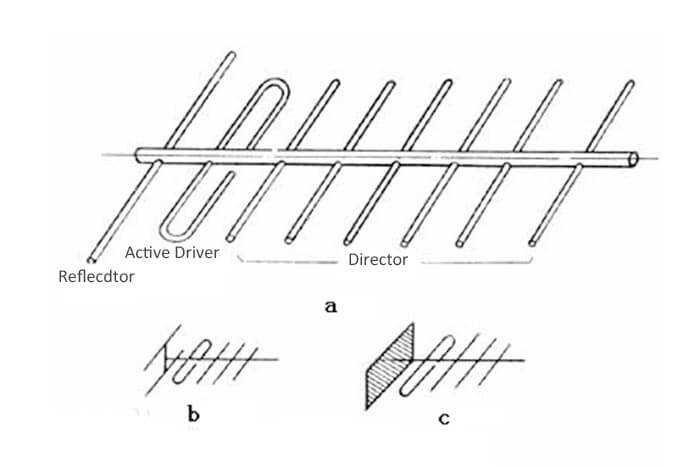
Yagi antenna also called the Yagi-Uda antenna, is a kind of directional antenna.
Yagi antenna is an active dipole driver (generally with a folded dipole), a passive reflector, and a number of passive feeder director antennas.
What are Yagi-Uda antenna characteristics?
Yagi antenna has the characteristics of high gain, wide working band, large front-to-back radiation ratio, and strong anti-interference ability. The antenna can effectively solve communication and data transmission problems. Effective suppression of side beam, more to achieve the best gain parameters.
Yagi antenna has the outstanding advantages of simple structure, convenient feeding, easy production, etc. It is widely used in meter waves, and decimeter waves.
Wavelength communication, radar, television, and other radio equipment.
The disadvantage of the yagi antenna is that it is difficult to adjust, and the frequency band is narrower, generally within 5%.
What is the Yagi antenna’s mechanical performance?
Yagi antenna adopts the feeder cable matching technology and the form of a stamping feed source, which can well ensure the consistency and waterproofing of the antenna.
The material of the Yagi antenna body is made of alloy aluminum after oxidation, which can prevent the antenna from acid rain, alkaline water, salt spray, and so on. Ensure long-term stable use in the harsh environment.
What kind of conditions is the Yagi antenna suitable for use?
Yagi antenna is more suitable for corridors, aisles, tunnels, long and narrow buildings, and connecting point-to-point outdoor connections of medium distance (for example, connecting two buildings of a commercial complex or campus) because of its signal transmission angle characteristics.
Attention must be paid to the rear beam, but the narrow beam of the Yagi antenna will reduce unwanted peripheral exposure in the direction of focus.
How far is the transmission distance of the Yagi antenna?
At a Yagi-to-Yagi antenna point-to-point visual distance, a transmission range of 1km can be achieved. If there are obstructions in between, such as buildings, trees, etc., it depends on the actual environment.
DIY Yagi antenna design program
Yagi antenna design is mainly based on the gain requirements after selecting the number of antenna elements, determining the length of each element, and the distance between the elements and other parameters.
Here are the 7 steps of the Yagi antenna design program.
Yagi antenna design program step 1, the director spacing selection
The choice of the director spacing has two options: one is the director spacing is not equal, with the increase of the number of director serial numbers, the adjacent director spacing increase other is the director spacing equal.
The former scheme is troublesome to adjust, and the latter is easy to adjust, so the equal spacing scheme is generally used. The director spacing is generally selected in the wavelength range.
When the spacing is larger, the main beam of the directional diagram is narrower, and the frequency response of the input impedance is smoother, but the second beam is larger; when the spacing is chosen, the second beam is lower, the anti-interference performance is better, but the gain and direction is worse.
If you consider the former, the spacing can be wavelength; if you consider the latter, the spacing can be less than the wavelength.
No matter what the case, the distance between the first director element and the active dipole driver element should be made smaller, generally taking ( ) other director spacing.
Yagi antenna design program step 2, reflector and active dipole driver spacing selection
The distance between the reflector and the active dipole driver generally goes to the wavelength. This spacing mainly affects the front and rear field strength ratio and input impedance of the Yagi antenna.
When the spacing in the wavelength, the front, and rear comparison is high, but the antenna input impedance is small (about 15-20 ohms); when the spacing is the wavelength, the front, and rear comparison is low, but the antenna input impedance is large (about 50-60 ohms), easy to match with coaxial cable.
Yagi antenna design program step 3, the choice of the length of the director
The choice of the length of director has two programs.
One is the length of each director, about taking the wavelength. The advantage of this Yagi antenna design program is easier to process and adjust, but the frequency band is narrower.
Another is that the length of each director with the serial number increases with a long to short gradual change.
First take the first director length for the wavelength, after the director length is decreasing by a shortening factor of 2-3%. The advantage of this program is a slightly wider band, but the debugging, and processing trouble. The practical use of the first program.
Yagi antenna design program step 4, the length of the reflector selection
Reflector length is generally chosen in the wavelength of the question. Its length can not be shorter than the design of the lowest frequency corresponding to 1/2 wavelength.
Yagi antenna design program step 5, passive dipole driver radius determination
The radius of the passive dipole driver is determined according to the requirements of the Yagi antenna passband. Usually, the radius of the dipole driver is chosen in 1/(500-80) wavelength.
Yagi antenna design program step 6, the structure and size of the active dipole driver
Active dipole drivers can choose a single half-wave dipole driver or folded dipole driver, the general length of the wavelength. The thicker the element, the length should be shorter.
Yagi antenna design program step 7, gain and main beam width estimation
Gain ≈ 10*(antenna length)/wavelength
Main beam width ≈ 55*square root (antenna wavelength/length)
Yagi antenna design formula calculation
The narrower the width of the main beam of the antenna, the higher the gain. For the general antenna, the following formula can be used to estimate its gain.
Gain/g (dbi) = 10lg{32000/(2θ3db,e×2θ3db,h)}
Where 2θ3db,e and 2θ3db,h are the antenna in the two main planes of the width of the beam; 32000 is the statistics out of the empirical data.
For a parabolic antenna, the following formula can be used to approximate the gain.
Gain/g(dbi)=10lg{4.5×(d/λ0)2}
Where d is the diameter of the paraboloid; λ0 is the center of the wavelength; 4.5 is the statistics out of the empirical data.
For the upright omnidirectional antenna, there is an approximate calculation formula
Gain/g (dbi) = 10lg{2l/λ0}
where l is the antenna length; λ0 is the central working wavelength.
Different elements of Yagi antenna design comparison
Antenna form | Number of reflectors | Number of directors | Number of active dipole drivers | Directionality factor |
Dipole Yagi antenna | 0 | 0 | 1 | 0dB |
Two-element Yagi antenna | 1 | 0 | 1 | 3~4.5dB |
Two-element Yagi antenna | 0 | 0 | 1 | 3~4.5dB |
Three-element Yagi antenna | 1 | 1 | 1 | 6~8dB |
Four-element Yagi antenna | 1 | 2 | 1 | 7~10dB |
Five-element Yagi antenna | 1 | 3 | 1 | 9~11dB |
From the above table, it can be seen that the more elements of the Yagi antenna, the stronger the directionality. But the increase of elements is not proportional to the directionality. When there are too many elements, it leads to a narrow working band, and the whole antenna size will be big.
In the short wave band, the wavelength is long, and the homemade yagi antenna is difficult, in the ultra-short wave band (VHF/UHF), because the wavelength is short, can be more convenient to homemade low-cost yagi antenna.
The mathematical calculation of the Yagi antenna is complicated, but many engineering or theory books give its size, as long as according to these data, you can make a pair of good Yagi antennas.
5 element yagi-uda antenna design
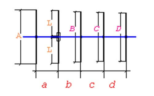
The picture is the schematic diagram of a 5-element Yagi antenna design
The five-element Yagi antenna design formula is:
A=1/2λ*98%, B=1/2λ*90%, C=1/2λ*88%, D=1/2λ*86%, L=1/4λ*95%, a=b=c=d=0.2λ
Yagi antenna design calculator
The following describes the calculation method for the Yagi antenna design element length.
- The reflector length is 0.52λ.(λ is wavelength)
- The director length is 0.95λ/2; the director width is 0.03λ; the director wiring opening width is generally taken 2.5cm.
- The length of the director is 0.4λ (for more than 10 elements, the length of the 3~4 directors at the farthest end is 0.2~0.3λ).
The spacing between the dipole director elements.
- The spacing between the first director and the feeder director is 0.1λ.
- The spacing between the second director and the first director is 0.12λ.
- The spacing between the third director and the second director is 0.13λ.
- The spacing between the fourth director and the third director is 0.15λ.
- The spacing between the fifth director and the fourth director is 0.16λ.
- The spacing between the sixth director and the fifth director is 0.2λ.
- The spacing between the seventh director and the sixth director is 0.3λ. 8.
- The spacing between the remaining directors is 0.325λ.
- The spacing between the reflector and the feeder director is 0.15λ.
Yagi antenna design, processing, and installation considerations
How to select Yagi antenna materials?
- For frequency below 400MHz, choose φ8~12 copper tube or aluminum tube for the director.
- Frequency in 400MHz above, the director chooses φ3 ~ 6 copper or aluminum tube.
- Antenna boom and bracket can choose metal tube or other materials.
What is the processing of Yagi antenna?
- The feeder director chooses φ8~12mm copper or aluminum tube, and can use a hot processing method according to the Yagi antenna design of the shape and size of the metal tube filled with relatively fine dry sand (pay attention to be loaded), heated and bent into shape, and then the sand will be poured out both, the feeder director select φ3-6mm copper or aluminum tube, which can use cold processing method according to the design of the shape and size with bender bent into shape.
- The reflector and director are welded on the antenna boom, and also can be fixed with screws, (note that all directors must be in a plane and antenna boom vertical, director and antenna boom insulation)
Diy Yagi-Uda antenna calculator
The following are the basic specifications considered in selecting Yagi Antenna and performing calculations in this yagi antenna calculator.
• Bandwidth
• Impedance
• Gain
• Front to Back Ratio
The yagi uda antenna calculators can be easy found on internet, this tool software use precautions: because the midpoint of the director position induction signal voltage zero point, therefore, no need to insulate with the beam; UHF/VHF band large number of users upright antenna, yagi antenna should let the director perpendicular to the earth.
What is the Yagi antenna design gain formula?
The antenna gain is a function of the number of dipole elements: GT = 1.66 * N where N is the number of elements in the Yagi antenna.
Three-element yagi antenna gain is about 6-8dB.
Four-element Yagi antenna gain is about 7-10dB;
Five-element Yagi antenna gain is about 9-11dB;
Nine-element Yagi antenna gain is about 13-15dB;
Eleven-element Yagi antenna gain is about 16-18dB;
…
433 MHz Diy Yagi Antenna UHF Yagi Antenna Design Example
UHF/VHF band radios are to be used for long-range directional communication.
The following introduces a homemade Yagi antenna working at 430-440MHz amateur frequency 433MHz with five elements, the antenna is simple to make, the total cost is less, and the specific production size is shown in the figure.
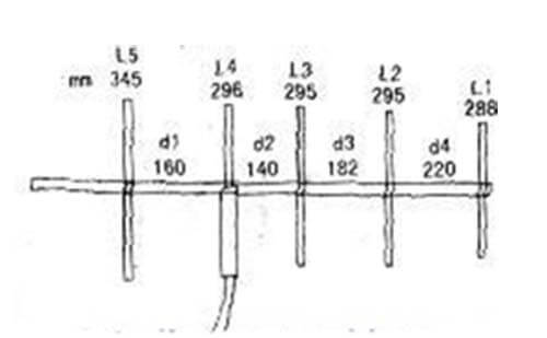
The director selected a section of model 50-9 or 50-11 lengths of about 350mm coaxial communication cable production, the length of the cable as the antenna director for 296mm, and the lower side of the length out of a small section is connected with the feed line connection section, can be stripped and 50Ω feed line directly connected or welded to the M-shaped high-frequency socket, to connect the feed line with M-shaped plug. The connection section is therefore free to choose the appropriate length depending on the feeder connection.
In the upper section of the cable, choose a length of 296 mm, i.e. 148mm where the shield is cut off and removed (leaving only the core and the inner insulation layer).
Then the lower half of the cable with a section of 148mm metal tube outside the cable, the upper part of the metal tube and cut off the shield fracture alignment and connected (cutting the shield can leave about 10mm more length in order to fold back and the upper part of the metal tube connected).
Metal tube here is to play the role of high-frequency choke so that most of the antenna current can not leak to the outer surface of the coaxial cable, so as to improve the antenna radiation direction map so that its characteristics are almost the same as the half-wave dipole antenna.
The thickness of the metal tube depends on the diameter of the selected coaxial cable size and difference.
Generally, as long as it can be set on the outer layer of the coaxial cable (it is recommended that the diameter of the metal tube is about 5mm larger than the outer diameter of the coaxial cable is better).
If the metal tube is thicker, it will move back and forth outside the cable, which is not conducive to fixing (this can be solved by winding tape outside the cable to increase the outer diameter of the cable).
Finally, the antenna director with tape or a heat-shrinkable tube can be sealed.
The antenna design working frequency is 438.5MHz, in the whole amateur segment 430MHz ~ 440MHz are used. In 438.5MHz measured standing, the wave is less than 1.2. By fine-tuning the length of the feed director and its spacing with L5, and L3, you can adjust the best resonant frequency and standing wave.
Besides the 433 MHz Yagi antenna design, C&T RF Antennas Inc also provides the Yagi-Uda antenna projects as the below.
VHF UHF Yagi antenna design
4G Yagi antenna design
2.4 GHz Yagi antenna design
HF Yagi antenna design
Dual-band Yagi antenna design
Dipole Yagi antenna design
Yagi TV antenna design
Etc
Yagi antenna installation and precautions
How to install the Yagi antenna?
For receiving TV signals, the oscillator and ground are installed in parallel. For receiving FM radio signals or for amateur radio transmission and reception, the oscillator and the ground should be installed vertically.
The installation of the bracket must be stable and wind-resistant, at the same time, we should pay attention to lightning protection, if the bracket is a metal tube and can be installed directly on the metal tube then the antenna’s high 1.5m metal rod, does lightning rod, pay attention to the bracket must be grounded reliably.
How to connect the Yagi antenna feeder cable?
Yagi antenna connected to the feeder director and feeder coaxial cable available 300Ω flat feeder cable directly connected, if using 75Ω or 50Ω coaxial feeder cable, shall add impedance converter.
Besides this How To Make a 433 MHz Yagi Antenna Design For A Long-range article, you may also be interested in the below articles.
55 Different Types of Antennas With Examples Used in Wireless Communication
4G vs. 5G: What is the difference between 4G and 5G?
How to Choose the Best Antenna for Lora?