Description
What is the Yagi Antenna 4G Long-range Outdoor Directional Antenna?
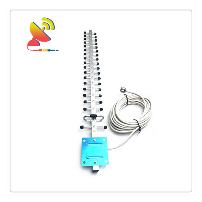
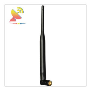
The Yagi Antenna 4G LTE antenna CTRF-ANTENNA-YAGI-7027-50-N is a Long-range Outdoor Directional Antenna Yagi antenna 4G antenna manufactured by C&T RF Antennas Inc.
The Yagi antenna not only has a unidirectional radiation and response pattern, but it concentrates the radiation and response. The more directors a Yagi has the greater the so-called forward gain.
As more directors are added to a Yagi, it becomes longer. Some Yagi antennas have as many as 10 or even 12 directors in addition to the driven element and one reflector. Long Yagis are rarely used below 50 MHz because at these frequencies the structure becomes physically unwieldy.
Yagi Antenna 4G Features
High Gain
Directional
Easy To Install
Fixed Location Buildings
C&T RF Antennas Inc provides internal & external antennas with antenna radio frequencies such as NFC, 169MHz, 230MHz, 315MHz, 433MHz, 868MHz, 915MHz, VHF&UHF, Lora, NB-IoT, ADS-B, GSM, GNSS, GPRS, 1.2 GHz, 1.4 GHz, 1.8 GHz, Wi-Fi 2.4 GHz, 5.8 GHz, Cellular 2G, 3G, 3.5 GHz, 4G LTE, GPS, 5G NR, 6G, etc.
C&T RF Antennas Inc. provides RF antennae with Omni & Directional antenna types such as Dipole Antennas, Whip Antennas, Marine Antennas, Router Antennas, MIMO Antennas, Combo Antennas, PCB Antennas, FPC Antennas, Spring Antennas, Magnetic Antennas, Sector Antennas, Yagi Antennas, and Accessories, etc, for IoT & M2M industries.
Contact us for the Yagi antenna 4G antenna datasheet, Yagi antenna 4G antenna pricing, Yagi antenna 4G antenna inventory, etc., or other Yagi antenna 4G antenna styles.
Yagi Antenna 4G Specifications
| Yagi Antenna 4G Electrical Specifications | |
| RF Antenna Type | Yagi Antenna |
| Model | CTRF-ANTENNA-YAGI-7027-50-N |
| Frequency | 698-806mhz/824-894mhz/925-960mhz/1710-1885mhz/1920-1980mhz/2110-2110mhz/2500-2690mhz |
| Gain | 25dBi |
| VSWR | ≤2.0 |
| Impedance | 50 Ω |
| Polarization | Vertical/Linear |
| Cable Type | RG58 |
| Connector | N-Type |
| Cable Length | 1.5M |
| Max Power | 50W |
| Lightning Protection | DC-Ground |
| Yagi Antenna 4G Mechanical Specifications | |
| Dimension | 60.5×9.8×1.6cm |
| Weight | Approx. 300g |
| Material | Aluminum |
| Operation Temperature | -40˚C~+85˚C |
| Storage Temperature | -40˚C~+80˚C |
| Units | 14 |
| Mounting | U Clamp/Adsorption |
| Safety Emission and other | RoHS Compliant |
How to design a Yagi Antenna?
As an electromagnetic transducer element, the position of the antenna in the entire radio communication system is very important. The quality of the antenna directly affects the distance and communication effect of the transmission and reception. It can be said that without the antenna, there will be no radio communication.
As a classic directional antenna, Yagi antennas are widely used in HF, VHF, and UHF bands. The Yagi antenna consists of an active vibrator (usually a folded vibrator), a passive reflector, and several passive directors arranged in parallel to form an end-fire antenna.
Principle of Yagi antenna
The principle of the directional operation of the Yagi antenna can be deduced in detail based on the electromagnetic theory. The wavelength λ is closely related to the electrical indicators of the antenna. The wire with a length slightly longer than an integer multiple of λ/4 is inductive, and the length is slightly shorter than λ/4 Wires of integer multiples are capacitive.
Since the main vibrator L adopts a half-wave symmetrical vibrator or a half-wave folded vibrator with a length of about λ/2, it is in a resonance state when working at the center frequency point, and the impedance appears as a pure resistance, while the reflector A is slightly longer than the main vibrator and is inductive.
Assuming that the distance between the two is λ/4, taking the receiving state as an example, the electromagnetic wave coming from a certain point in front of the antenna will first reach the main vibrator and generate induced electromotive force ε1 and induced current I1.
After a distance of λ/4, the electromagnetic wave square Reaches the reflector, and induced electromotive force ε2 and induced current I2 are generated. Due to the distance of λ/4 in space, ε2 lags behind ε1 by 90°.
In addition, since the reflector is inductive I2 lags behind ε2 by 90°, I2 lags behind ε1 by 180°, and the reflector-induced current I2 generates radiation to reach the main oscillator. The magnetic field H2 lags behind I2 by 90°. According to the law of electromagnetic induction, H2 is in the main oscillator.
The induced electromotive force ε1′ generated by the above is 90° lagging behind H2, that is, ε1 lags 360° behind ε1, that is, the induced electromotive force ε1′ generated by the reflector in the main oscillator is in phase with the induced electromotive force ε1 directly generated by the electromagnetic signal source, and the antenna output The voltage is the sum of the two.
In the same way, it can be deduced that for the signal from a certain point behind the antenna, the induced electromotive force generated by the reflector in the main vibrator and the induced electromotive force directly generated by the signal is in the opposite phase, which has the effect of offsetting the output.
The directors B, C, D, etc. are all slightly shorter than the main vibrator, and the impedance is capacitive. Assuming that the distance between the vibrators b, c, and d is also equal to λ/4, the signal from the director to the front can also be derived according to the above method Play the role of enhancing the antenna output.
In summary, the reflector can effectively eliminate the back lobe of the antenna pattern, and work with the director to enhance the sensitivity of the antenna to the forward signal, so that the antenna has strong directivity, and the antenna gain is improved.
For the launch state, the derivation process is the same. In the actual production process, through careful design and proper adjustment of the length and spacing of each vibrator, it is possible to obtain a Yagi antenna that works at different center frequencies, has a certain bandwidth, a certain impedance value, and a better end-fire pattern.
Yagi antenna production process
The structure of the Yagi antenna is shown in the figure below. It consists of an active vibrator, a reflector, and several directors. Among them, the reflector slightly longer than the active vibrator plays the role of reflecting energy, and the director which is slightly shorter than the active vibrator plays the role of guiding energy.
The reflectors and directors on both sides of the active oscillator make the original two-way radiation into one-way radiation to improve the gain of the antenna. Yagi antennas are simple in structure, convenient to feed, and have high gain, and are widely used in VHF/UHF frequency bands.
-
433MHz antenna size
The number, length, and spacing of the Yagi antenna elements have a great impact on the antenna gain, front-to-rear radiation ratio, and bandwidth. The theoretical calculation of the size of the Yagi antenna is more complicated.
In most cases, some approximate formulas and empirical data are used for preliminary selection or modified on the basis of a finished antenna, and then the relevant data are determined after repeated adjustments through experiments.
The size of the Yagi antenna needs to be compromised from the various performance indicators of the antenna. The length of the antenna reflector is 35 cm (0.5λ, wavelength λ=70cm), the lengths of the three directors are equal, all of which is 31cm (0.44λ), the length of the active oscillator is temporarily set to 34cm (0.486λ), the actual length It must be determined in the antenna adjustment.
The pitch of the director can be selected as a variable pitch or an equal pitch. The unit spacing can be selected from 0.1λ to 0.34μm. When the distance between the directors is large, the antenna gain is high; when the distance is small, the frequency band characteristics of the antenna are good.
The distance of the antenna director is 0.2λ. It should be noted that the distance between the first director and the active vibrator should be smaller, generally 0.14λ. The distance between the reflector and the active oscillator is also 0.2λ.
2. γ matching
The impedance matching problem must be solved first when the antenna is connected to the feeder. The so-called impedance matching is to transform the input impedance of the antenna to the characteristic impedance value of the feeder connected to it (usually 50Ω) so that all the power output by the radio can be emitted from the antenna.
There are many forms of matching methods for Yagi antennas. The core wire of the coaxial cable is connected to the gamma rod through a variable capacitor, and the cable shielding layer is connected to the center of the active vibrator. The shorting bar connects the active vibrator and the gamma rod and can move.
Adjusting the capacity of the variable capacitor and the position of the shorting bar can make the antenna match. γ matching is an unbalanced type and can be directly connected to a coaxial cable. It is a very convenient matching method that amateur radio enthusiasts love.
3. Antenna production
The materials required for antenna production are shown in the following table. All vibrators are made of Φ3mm copper welding rods, and the crossbars can be 15 mm x 15 mm square tubes or aluminum alloy materials with a length of 70cm.
First, cut 6 copper rods according to the dimensions in Table 1, and make punch marks on the corresponding positions of the square tubes. Use a Φ3mm drill bit, and use a bench drill to punch through the square tube in 5 holes so that the copper electrode can just be inserted into the crossbar.
To facilitate adjustment and disassembly, drill a hole above the vibrator, weld a nut, and tighten the screw to fix the vibrator. Note that it is best to use a bench drill to drill the square pipe. It is not easy to control the direction with a pistol drill, and it is easy to cause the vibrator to tilt.
Find a piece of 60 mm x 15 mm, 1mm thick iron sheet, bend it at a right angle, and drill a hole. The long side is fixed on the crossbar, and the short side is equipped with a BNC socket. The vertical distance from the center of the socket to the active vibrator is about 20mm. File off the paint between the iron sheet and the square tube to ensure good contact.
The short-circuit bar can be made of two pieces of aluminum or copper with a size of 30 mm and 10 mm and a thickness of about 1-2 mm. Punch a hole in the middle of the two aluminum sheets, install a screw, and clamp it on the active vibrator and the gamma rod, and adjust the distance between the two copper rods to 20mm. Finally, solder the ceramic capacitor to the core wire and γ rod of the BNC socket, and the antenna production is completed.
4. Antenna adjustment
There are many factors that affect the performance of the Yagi antenna, and the adjustment of the Yagi antenna is more complicated than other antennas. Under amateur conditions, we mainly adjust the two parameters of the antenna: resonance frequency and standing wave ratio.
That is, adjust the resonant frequency of the antenna near 435MHz, and make the standing wave ratio of the antenna as close to 1 as possible.
Set up the antenna about 1.5m from the ground, and connect the standing wave meter to start measurement. In order to reduce the measurement error, the cables connecting the antenna to the standing wave meter and the radio to the standing wave meter should be as short as possible.
This antenna can be adjusted in three places: the capacity of the fine-tuning capacitor, the position of the shorting bar, and the length of the active oscillator.
The specific adjustment steps are as follows:
(1) Fix the shorting bar at 5~6cm away from the crossbar;
(2) Adjust the transmitter frequency to 435MHz, adjust the ceramic capacitor to minimize the standing wave of the antenna;
(3) Measure the standing wave of the antenna from 430 to 440 MHz, every 2 MHz, and plot or list the measured data.
(4) Observe whether the frequency (antenna resonance frequency) corresponding to the minimum standing wave is near 435MHz. If the frequency is higher or lower, you can replace it with an active vibrator that is a few millimeters longer or shorter to measure the standing wave again;
(5) Change the position of the shorting bar slightly, and fine-tune the ceramic capacitor repeatedly to make the antenna standing wave as small as possible near 435MHz.
Adjust the antenna one at a time, so that it is easy to find the law of change. Due to the high operating frequency, the adjustment range should not be too large. For example, the adjusted capacity of the fine-tuning capacitor connected in series to the γ rod is about 3 to 4 pF, and changing a fraction of a few picofarads (pF) will cause a great change in the standing wave.
In addition, many factors such as the length of the crossbar and the position of the cable will also have a certain impact on the measurement of the standing wave, which we need to pay attention to during the adjustment process. It is best to measure the standing wave (SWR) after the antenna is adjusted.
Reviews
There are no reviews yet.