Flexible printer circuit (FPC) board serves planar wireless antenna design. Effectively to supersede the antenna based on the traditional fixed printer circuit board (PCB) implement, and then provide a free dimension of the antenna and wireless system integration to designer.
What material is used for FPC antenna?
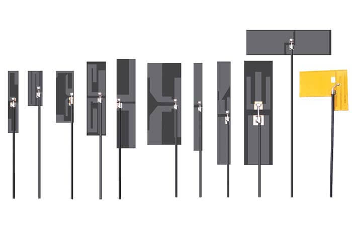
The main material is double-sided tape + low-loss yellow cover film + (line copper + glue + high-frequency dielectric polyimide substrate + glue + line copper) + low-loss yellow cover film.
Since the adhesive of the FPC antenna is affixed to fingers or other substances, the secondary adhesiveness of the adhesive will be reduced; if the corners of the copper cloth are bent, they can be attached to the surface of the shell with a smaller curved radius.
It is also susceptible to warping due to bending stress. Therefore, during the operation of separating the adhesive paper from the PFC antenna, avoid bending at both ends of the antenna or touching the adhesive on both ends of the antenna with your fingers, because these ends are usually the ones that receive the greatest bending stress at the end. In place, be sure to keep the adhesive on these two ends clean and avoid creases on the copper cloth areas at these two ends.
FPC antennas are very thin, usually, only 0.15 mm, and have a peelable strip and an adhesive area, which can be fixed in small electronic devices in various configurations. They are supplied with a cable and a connector for fixing them to the bottom cover or housing of the manufacturer’s electronic product. An FPC antenna is very light, less than 1 gram.
FPC antenna advantages is no ground.
The working principle of FPC antenna and surface mount device (SMD) chip antennas is different. The SMD antenna uses the installed ground plane to radiate, and its working principle is reciprocating. The dipole antenna uses two radiators, and the length of each radiator is related to the wavelength of the frequency used by the antenna. Embedded antennas have a heat sink within their mass range, and they use an area on the PCB board as their counterpoint, usually called a ground plane.
For SMD antennas, the length of the ground plane is directly related to the wavelength of the antenna. The correct ground plane length must be provided in the design so that the antenna can operate with good efficiency.
FPC antennas are different at this point in that they do not need a ground plane to radiate. Therefore, they allow the designer to freely arrange the components in the circuit in the design.
But the coaxial cable becomes part of the antenna. Therefore, when designing the antenna cable extender, care should be taken to keep this part of the antenna away from other components that may generate noise and interference.
How to place the FPC antenna?
Because the ground plane is not a design consideration for FPC antennas, the size of the host PCB is not a factor like SMD or chip antennas. However, the placement of FPC antennas still needs to follow some basic rules, because most antennas are sensitive to the environment.
The antenna will radiate in six spatial directions, front, back, left, right, up, and down. Ideally, there should be no obstacles in at least three to five directions, which will allow the antenna to work effectively. For other directions with obstacles on the radiation path, there should still be a minimum gap, which will be defined in the antenna manufacturer’s datasheet.
The plastic casing of the device will not act as an obstacle unless the material for the casing is glass-filled or has been painted with metallic paint. Metal objects and components close to the FPC antenna, such as data lines and printed circuit boards (PCB), are usually the culprits that block the signal.
The direction of FPC antenna information regarding metal keep out requirement
The shape of the device will determine the ideal orientation of the FPC antenna relative to the PCB board. The position of the antenna relative to the PCB board will depend on the proximity of the ground wire.
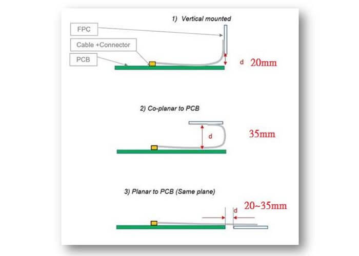
The three common configurations information regarding metal keep out requirement of the FPC antenna on the PCB board.
No matter which solution is chosen, distance (d) has become a key dimension in the design. This will be specified in the antenna manufacturer‘s datasheet.
The I-PEX connector cable of the antenna connects it to the design. The characteristic impedance of all transmission lines in the product is designed to be 50Ω and should be kept as short as possible. All other parts of the radiofrequency system, such as transceivers and power amplifiers, should also be designed to have an impedance of 50Ω.
We recommend using a commercial RF design package to create the transmission line layout, taking into account PCB thickness, copper thickness, and dielectric constant. The program will calculate the recommended width of the transmission line and the appropriate space between the reference ground planes on both sides of the antenna feeder to maintain a 50-Ω system impedance.
What is differentiate FPC antenna and PCB antenna?
What is a PCB antenna?
The PCB Trace antenna is embedded into the PCB during the manufacturing process. The PCB board antenna can operate within a wide bandwidth (if optimally tuned). Commands a high level of strength and network reliability (if optimally tuned). PCB Trace Antennas have a thin profile (two-dimensional).
PCB is an important electronic component, support for electronic components, and a carrier for the electrical connection of electronic components. Because it is made by electronic printing, it is called a printed circuit board.
After electronic equipment adopts printed boards, due to the consistency of similar printed boards, manual wiring errors can be avoided, and electronic components can be automatically inserted or mounted, automatic soldering, and automatic detection, ensuring the quality of electronic equipment, Improve labor productivity, reduce costs, and facilitate maintenance.
Printed boards have developed from single-layer to double-sided, multi-layer, and flexible, and still maintain their respective development trends. Due to the continuous development of high precision, high density, and high reliability, continuous reduction in size, cost reduction, and performance improvement, the printed circuit board will still maintain a strong vitality in the future development of electronic equipment.
The reason why PCB can be used more and more widely is that it has many unique advantages, which are summarized as follows.
Can be high-density
For decades, the high density of printed boards has been able to develop along with the improvement of integrated circuit integration and the advancement of mounting technology.
High reliability
Through a series of inspections, tests and aging tests, the PCB can work reliably for a long time (usually 20 years).
Designability
For PCB antenna performance (electrical, physical, chemical, mechanical, etc.) requirements, printed board design can be achieved through design standardization, standardization, etc., with short time and high efficiency.
Manufacturability
With modern management, standardized, scaled (quantitative), automated, and other production can be carried out to ensure product quality consistency.
FPC antenna is not only a flexible circuit board but is also an important design method of the integrated circuit structure. This structure can be combined with other electronic product designs to build a variety of different applications.
From this point on Look, the FPC antenna and hardboard are very different. For hard boards, unless the circuit is made into a three-dimensional form by means of potting glue, the circuit board is generally flat. Therefore, to make full use of the three-dimensional space.
FPC is a good solution. In terms of hard boards, the current common space extension solution is to use slots to add interface cards, but the FPC antenna can be made with a similar structure as long as the adapter design is used, and the directional design is also more flexible.
Using one piece of connection FPC antenna, two pieces of hard boards can be connected to form a set of parallel circuit systems, and it can also be turned into any angle to adapt to different product shape designs.
FPC antenna can of course use a terminal connection for line connection, but it is also possible to use soft and hard boards to avoid these connection mechanisms. A single FPC antenna can use layout to configure many hard boards and connect them. This approach eliminates connectors and terminals, which can improve signal quality and product reliability.
FPC antennas can make thin circuit boards because of the material properties, and thinning is one of the important needs of the current electronics industry. Because the FPC antenna is made of thin-film materials, it is also an important material for thin design in the future electronic industry. Since the heat transfer of plastic materials is very poor, the thinner the plastic substrate is, the more favorable it is for heat dissipation.
Generally, the difference between the thickness of the FPC antenna and the rigid board is more than tens of times, so the heat dissipation rate is also tens of times the difference. FPC antenna has such characteristics, so many of these high-wattage parts FPC antenna assembly products will be attached with metal plates to improve the heat dissipation effect.
For the FPC antenna, one of the important features is that when the solder joints are closed and the thermal stress is large, the stress damage between the joints can be reduced due to the elastic characteristics of the FPC antenna. This kind of advantage can absorb the thermal stress, especially for some surface mounts, this kind of problem will be reduced a lot.
Is the FPC antenna suitable for your design?
For small PCBs, SMD antennas may be the most obvious choice, but FPC antennas are widely used in applications with insufficient space.
Off-the-shelf FPC antennas are not recommended for the smallest devices, but there are many applications where the FPC antenna can work well. They are a particularly useful option for designs where the length and space of the ground plane are limited.
C&T RF Antennas Inc is the FPC antenna, PCB antenna designer, and manufacturer, contact us for more information you may need.
Besides the What Is FPC Antenna article, you may also be interested in the below articles.
What is the difference between WIFI and WLAN?
Summary of 41 Basic Knowledge of LTE
What Is The 5G Network Slicing?