Description
What is 150W Power Amp 300-500MHz UHF Amplifier?
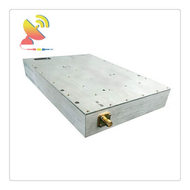
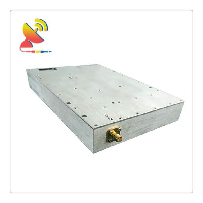
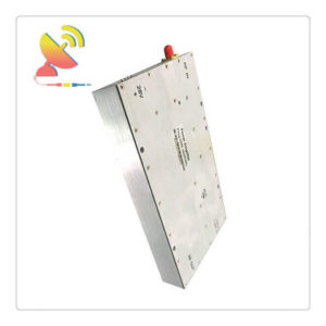
The 150W Power Amp 300-500MHz UHF Amplifier CTRF-ANTENNA-AMP-AP-3050-150W RF Amplifier UHF 300-500MHz 150Watts RF Power Amplifier is an extra-wide band UHF power amplifier with 300-500Mhz includes 315Mhz, 400Mhz, 433MHz, 470Mhz, 500MHz frequencies, and 150 watts output.
150W Power Amp 300-500MHz UHF RF Amplifier Is Supplied At C&T RF Antennas Inc. we provide RF products with RF antennas, Antenna Accessories, Amplifiers, And Repeaters.
C&T RF Antennas Inc provides internal & external antennas with antenna radio frequencies such as NFC, 169MHz, 230MHz, 315MHz, 433MHz, 868MHz, 915MHz, VHF&UHF, Lora, NB-IoT, ADS-B, GSM, GNSS, GPRS, 1.2 GHz, 1.4 GHz, 1.8 GHz, Wi-Fi 2.4 GHz, 5.8 GHz, Cellular 2G, 3G, 3.5 GHz, 4G LTE, GPS, 5G NR, 6G, etc.
C&T RF Antennas Inc. provides RF antennae with Omni & Directional antenna types such as Dipole Antennas, Whip Antennas, Marine Antennas, Router Antennas, MIMO Antennas, Combo Antennas, PCB Antennas, FPC Antennas, Spring Antennas, Magnetic Antennas, Sector Antennas, Yagi Antennas, and Accessories, etc, for IoT & M2M industries.
To contact Us For 150W Power Amp 300-500MHz UHF RF Amplifier Price, 150W Power Amp datasheet, 150W Power Amp inventory, etc.
RF Amplifier UHF 300-500MHz 150W Power Amp Technical Specifications:
| Frequency(MHz) | 300-500 |
| Output Power(dBm) | 52±1(150watts) |
| Max input power | 15dBm |
| ALC Range(dB) | ≥25 |
| Gain(dB) | 55±1 |
| Gain Adjustment Range(dB) | >30/1dB step or Customized |
| Gain Adjustment Linearity(dB) | ≤±1 |
| Impedance(ohm) | 50 |
| VSWR | ≤1.5:1 |
| Voltage(V) | DC+28-32V |
| Power Current | ≤11A |
| RF Connector | SMA-50K or other Customized |
| RF monitor(MON) | Output signal detection port, the test value=actual power-50db |
| Working Temperature | -20~+55 degree |
| Operating Humidity | 0 to 90%, relative |
| weight | ≤1.5KG |
| Surface Color | Metal color conductive oxide and other color customized |
| Switch | Turn off at input power ≤-45dBm |
Led status
| LED1 | OFF | PA works normally. |
| Light | ALC>1 | |
| LED2
LED3
|
LED2 light on and off each 1second and LED3 Light | PA works normally.
|
| LED2 off and LED3Light | The PA works normally, but no input signal or input signal is less than -45dbm. | |
| LED2 Fast flash and LED3 Light | Input buffer (digital attenuator slowly decreases). | |
| LED2 light on and off each 1second and LED3 off | The PA power off due to over-temperature automatically restarts when the temperature drops to 55 degrees | |
| LED2 light on and off each 0.5second and LED3 off | Wait for restart (PA will wait for 3min,5min,10min,10min,20min when PA power off due to Over current, overvoltage, overpower, ing or VSWR, then automatically restart after PA ) | |
| LED2 light and LED3 Light | It restarts successfully but no input signal after module protection | |
| LED2 light and LED3 off | Restart failure (if 5 times cannot restart successfully and prompt failure, it needs manual exclusion). |
Power amplifier circuit Less heat dissipation
The heat dissipation problem of BJT is in the power amplifier circuit, a considerable amount of power is consumed on the collector junction of the tube, which increases the junction temperature and the temperature of the case.
In order to make full use of the allowable tube consumption and make the tube output enough power, the heat dissipation of the amplifying device becomes an important problem.
Preferences
In the power amplifier circuit, in order to output larger signal power, the tube must withstand a high voltage and a large current through which the power tube is likely to be damaged. Therefore, the parameter selection and protection of the power tube cannot be ignored.
Analysis task
The analysis tasks of the power amplifier circuit are the maximum output power, the highest efficiency, and the safe working parameters of the power transistor. In the analysis method, because the pipe works under a large signal, the graphical method is usually used.
Working status
Class A: In the amplifier circuit, when the input signal is a sine wave if the transistor is turned on during the entire period of the signal (that is, the conduction angle θ=360°), it is said to be working in a Class A state;
Type B: If the transistor is only turned on during the positive or negative half cycle of the signal (ie θ=180°), it is said to be working in the Type B state;
Class A and B: If the on-time of the transistor is longer than half a cycle and less than one cycle (that is, between θ=180°~360°), it is said to be working in a Class A and B state;
Category C: If the transistor has only a conduction time of less than half a cycle (that is, θ=0°~180°), it is said to work in a category C state.

Reviews
There are no reviews yet.