Description
What is a 433MHz RF Power Amplifier?
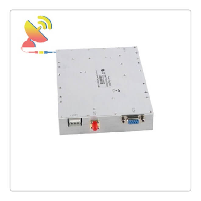
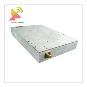
C&T RF Antennas Inc’s CTRF-ANTENNA-AMP-PA-0433-50W Item PA amplifier 433MHz RF Power Amplifier is a UHF band power amplifier that operates across an extremely wide frequency band from 400 to 450 MHz Lora amplifier.
Typical performance includes 5dBm input power, 50dBm output power, and 100W power. The 433MHz RF Power Amplifier design exhibits a very flat gain response across the entire frequency band.
PA Amplifier 433MHz RF Power Amplifier is supplied by C&T RF Antennas Inc., we provide RF products with RF antennas, Antenna Accessories, Amplifiers, And Repeaters.
C&T RF Antennas Inc provides internal & external antennas with antenna radio frequencies such as NFC, 169MHz, 230MHz, 315MHz, 433MHz, 868MHz, 915MHz, VHF&UHF, Lora, NB-IoT, ADS-B, GSM, GNSS, GPRS, 1.2 GHz, 1.4 GHz, 1.8 GHz, Wi-Fi 2.4 GHz, 5.8 GHz, Cellular 2G, 3G, 3.5 GHz, 4G LTE, GPS, 5G NR, 6G, etc.
C&T RF Antennas Inc. provides RF antennae with Omni & Directional antenna types such as Dipole Antennas, Whip Antennas, Marine Antennas, Router Antennas, MIMO Antennas, Combo Antennas, PCB Antennas, FPC Antennas, Spring Antennas, Magnetic Antennas, Sector Antennas, Yagi Antennas, and Accessories, etc, for IoT & M2M industries.
433MHz RF Power Amplifier Applications
Electronic Warfare
Electronic Countermeasures
OC192 Fiber Optic
Optical Modulator Driver Applications
Microwave Radio
VSAT
Radar
Space Systems
Test Instrumentation
Telecom Infrastructure
The basic applications of the 433MHz RF Power Amplifier include driving to another high-power source, driving a transmitting antenna, and exciting microwave cavity resonators. Among these applications, driving transmitter antennas is the most well-known.
The transmitter-receivers are used not only for voice and data communication but also for weather sensing (in the form of radar).
433MHz RF Power Amplifier Input/output ports are matched for 50 ohms and are AC coupled. The design also incorporates integrated bias sequencing circuitry and voltage regulators to allow for flexible biasing for both the negative and positive voltage supplies.
The bench-top package is hermetically sealed with field-replaceable SMA connectors and comes with a heat sink. This rugged package assembly is designed to meet MIL-STD-883 test conditions for Hermeticity and Temperature Cycle.
This 433MHz RF Power Amplifier UHF Power Amplifier Module is part of C&T’s expanding line of Amplifier offerings. These modules offer very wide Frequency Range coverage and outstanding electrical performance in the band.
RF power amplifiers using LDMOS (laterally diffused MOSFET) are the most widely used power semiconductor devices in wireless telecommunication networks, particularly mobile networks.
LDMOS-based RF power amplifiers are widely used in digital mobile networks such as 2G, 3G, and 4G.
Our RF module and rack-mounted RF and microwave systems incorporate state-of-the-art GaN, LDMOS, MOSFET, GaAsFET, and bipolar device technologies.
Our extensive library of product designs includes over four hundred documented solutions ranging from basic-function RF Power Amplifier modules to complete, multifunction HPA systems with embedded software for local and remote control and monitoring.
433MHz RF Power Amplifier Specifications:
| Frequency(MHz) | 400-450 |
| Input Power | ≤0-5dBm |
| Output Power(dBm) | 50 |
| Gain(dB) | 50 or Customized |
| ALC Range(dB) | ≥25 |
| Efficiency | 35% |
| Impedance(ohm) | 50 |
| VSWR | ≤1.5:1 |
| Voltage(V) | 28 VDC |
| RF Connector | SMA-Female |
| Monitor interface | RS232 |
| Working Temperature | -25~+55 degree |
| Storage Temperature | -45 to +85 degree |
| Operating Humidity | 0 to 90%, relative |
| Protection | High temperature, high VSWR, forward power detection, reverse power detection |
| Weight | ≤1.5kg |
| Cooling | External heatsink |
433MHz RF Power Amplifier Monitoring Function Description:
| No. | Monitoring function | Description | |
| 1 |
query |
PA ALARM | When an alarm amplifier failure |
| 2 | SWR ALARM | Amplifier output reflection is too large, VSWR exceeds 3:1, an
alarm is generated |
|
|
3 |
Over-temperature alarm |
Module internal temperature exceeds 85 ℃, generates an
alarm and turn off the amplifier until the temperature returns to below 65 ℃, re-open the amplifier |
|
| 4 | Over-output power alarm | When the output power exceeds the nominal full power 2dB is
an alarm |
|
| 5 | Input power detection | Accuracy of ± 1dB | |
| 6 | Reverse power detection | Accuracy of ± 1dB | |
| 7 | output power detection | Detecting the actual output power amplifier, Accuracy of ± 1dB | |
| 8 | Temperature detection | Detection module operating temperature, detection range: -25
~ +90 ℃, Accuracy of ± 3 ℃ |
|
| 9 | SWR | Detecting amplifier output port VSWR range of 1.2 ~ 4.0 | |
| 10 |
query and set |
PA attenuator Set and
query |
Set and query the value of ATT |
| 11 | PA switching query and set | Query and set the state open tube amplifier | |
PA Amplifier 433MHz RF Power Amplifier Is Available At C&T RF Antennas Inc. We Offer 433MHz RF Power Amplifier Inventory, 433MHz RF Power Amplifier Pricing, & Datasheets For The 433MHz RF Power Amplifier or other RF Amplifiers.
Contact us for more details on the 433MHz RF Power Amplifier price, 433MHz RF Power Amplifier specifications, etc.
Important parameters of the power amplifier
1. Input sensitivity
Input sensitivity refers to the minimum input signal level required by the power amplifier. It is a necessary condition for the sound source signal to be amplified enough to promote the power amplifier.
2. Harmonic distortion
Harmonic distortion is an extremely important indicator of power amplifiers. Harmonic distortion is a kind of nonlinear distortion. It is caused by the nonlinear characteristics of the amplifier when it is working.
The result of distortion is that new harmonic components are generated, which makes the sound The original tone is lost, and the sound is broken and harsh in severe cases.
Harmonic distortion is divided into odd and even harmonics. Odd harmonics can make people noisy, disgusting, and easy to be perceived. Some power amplifiers sound annoying and tired, which is caused by greater distortion.
The greater impact on the power amplifier is the degree of distortion. Generally, high fidelity requires harmonic distortion below 0.05%, the lower the better.
In addition to harmonic distortion, there are intermodulation distortion, crossover distortion, clipping distortion, transient distortion, phase distortion, etc., which are the culprits that affect the quality of the power amplifier.
3. Output power
A. Rated output power, called (RMS), refers to the higher power that the audio signal output by the amplifier can output within the total harmonic distortion range. It is generally 0.707 times the peak value of the AC signal.
B. Average power. Average power generally refers to the average power consumption of each frequency point. It is a bit similar to the rated output power, but it generally requires time.
C. Peak output power. The greater music power that the power amplifier can output is called peak output power. It does not consider distortion, usually about 1.414 times the (RMS) power.
D. Peak-peak power, refers to the power from the peak of the positive voltage to the peak of the negative voltage, which is four times the peak output power. It appeared because of the manufacturer’s commercial purpose and had no practical significance.
4. Signal-to-noise ratio
The larger the value of the signal-to-noise ratio, the better, generally expressed in (S/N), expressed in decibels of the ratio of signal power Ps to noise power Pn, S/N=10lgPs/Pn=20lgVs/Vn (dB) Vs and Vn are signal voltage and noise voltage respectively.
As the signal-to-noise ratio and the input signal level increase, the signal-to-noise ratio gradually increases, but when the input signal level reaches a certain value, the signal-to-noise ratio basically remains unchanged.
According to the current high-fidelity requirements, the signal-to-noise ratio should be above 90dB. Some signal-to-noise ratios are followed by A-weighting. A weighting refers to the result of measuring the noise signal through a weighting network.
Because people are relatively insensitive to noise in high and low-frequency bands, such a Weighting method. The weighted noise more intuitively represents the noise signal condition that people actually feel.
In short, the larger the signal-to-noise ratio, the smaller the noise mixed in the signal, the better the sound quality, and the clear, clean, and layered music will be played back.
5. Frequency response
In the early stage of frequency response, it is called power bandwidth, which refers to the 1/2 rated power bandwidth of the power amplifier when the harmonic distortion does not exceed the specified value. Power bandwidth.
6. Damping coefficient
The damping coefficient is mainly for low frequencies and is an extremely important technical parameter that directly affects the bass sound quality.
As we all know, the larger the caliber of the speaker, the better the bass, but the larger the cone, the greater the inertia of its motion.
This inertia makes it difficult to move in sync with the audio signal, and the sound often appears muddy, especially In the low frequency of 100-400Hz, it is easy to cause sound coloring, making people sound unclear and unnatural.
The woofer of some modified cars vibrates more when the low-frequency signal is strong, and the bass tail is serious, which is caused by the inertia of the cone.
During the design of the power amplifier, the engineers took some technical measures for the power amplifier, such as choosing multiple tubes in parallel, low internal resistance (milliohm) high power tubes, increasing the working voltage, choosing high-quality wires, etc.,
And trying to improve the damping coefficient so that it can target the speakers The inertial movement produces the resistance effect, which makes the movement of cone move synchronously with the audio signal, and as far as possible to make the cone return to zero position (i.e. the center position) soon after the end of the driving signal.
This blocking effect is the damping coefficient (Damp Factor), D=Rs/Ri, Rs=speaker impedance, Ri=power amplifier output internal resistance, the larger the D, the better the sound cone and signal synchronization effect, the purer and cleaner the bass, the better the playback effect.
7. Slew rate
The conversion rate of the power amplifier greatly affects the quality and performance of treble playback. The faster the conversion rate, the better the treble sound quality, and the more accurately the fleeting high-frequency information can be captured.
High-quality power amplifiers can achieve more than ten to tens of V/us. Low and mid-range power amplifiers are generally not marked. The value of this conversion rate is closely related to the design and materials, but it should not be too high.
The generation of supersonic signals above 20KHz that cannot be heard by human ears not only has no effect on improving the sound quality but also easily burns the tweeter.
Reviews
There are no reviews yet.