Description
What is a 300-500 MHz UHF Amplifier Wideband Power Amplifier?
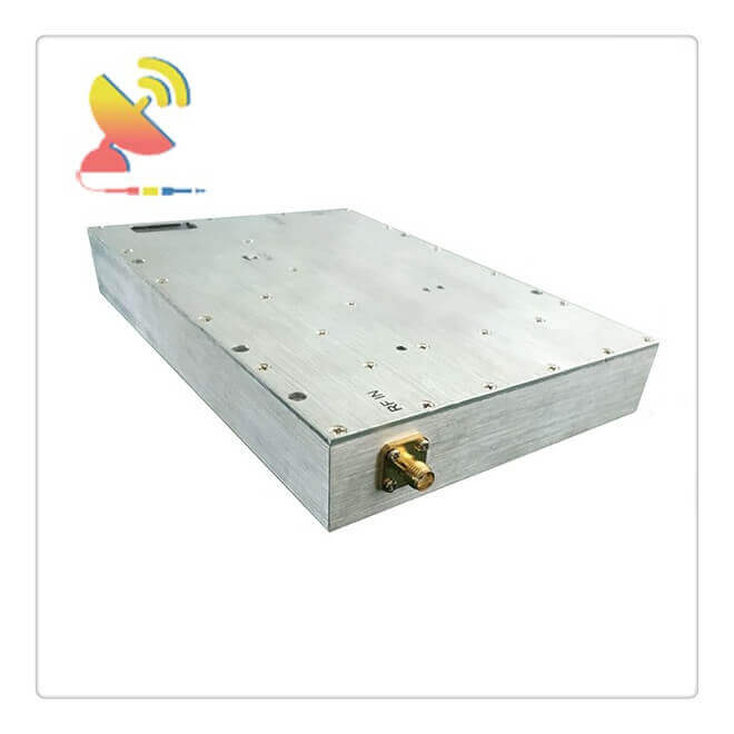
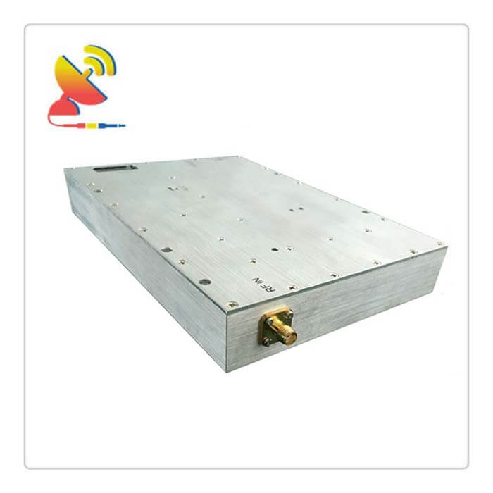
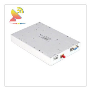
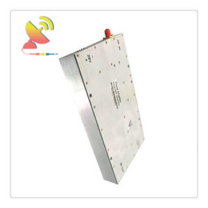
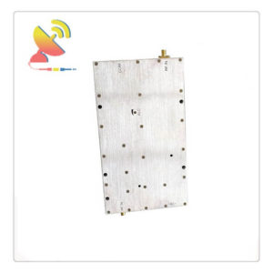
The Wideband Power Amplifier CTRF-ANTENNA-AMP-PA-300-500-150W RF Amplifier UHF 300-500MHz 150Watts RF Power Amplifier is an ultra-wideband power amplifier with 300-500Mhz includes 400MHz, 402Mhz, 433MHz, 435Mhz frequencies, and 150 watts output Wideband Power Amplifier supplied by C&T RF Antennas Inc.
300-500MHz Wideband Power Amplifier RF Amplifier UHF 150Watts RF Power Amplifier Is Supplied By C&T RF Antennas Inc.
We provide RF products with RF antennas, Antenna Accessories, Amplifiers, And Repeaters.
C&T RF Antennas Inc provides internal & external antennas with antenna radio frequencies such as NFC, 169MHz, 230MHz, 315MHz, 433MHz, 868MHz, 915MHz, VHF&UHF, Lora, NB-IoT, ADS-B, GSM, GNSS, GPRS, 1.2 GHz, 1.4 GHz, 1.8 GHz, Wi-Fi 2.4 GHz, 5.8 GHz, Cellular 2G, 3G, 3.5 GHz, 4G LTE, GPS, 5G NR, 6G, etc.
C&T RF Antennas Inc. provides RF antennae with Omni & Directional antenna types such as Dipole Antennas, Whip Antennas, Marine Antennas, Router Antennas, MIMO Antennas, Combo Antennas, PCB Antennas, FPC Antennas, Spring Antennas, Magnetic Antennas, Sector Antennas, Yagi Antennas, and Accessories, etc, for IoT & M2M industries.
Contact Us For The Wideband Power Amplifier Price, Wideband Power Amplifier datasheet, Wideband Power Amplifier inventory, or other frequency Wideband Power Amplifier design.
300-500 MHz UHF Amplifier Wideband Power Amplifier Technical Specifications:
| Frequency(MHz) | 300-500 |
| Output Power(dBm) | 52±1(150watts) |
| Max input power | 15dBm |
| ALC Range(dB) | ≥25 |
| Gain(dB) | 55±1 |
| Gain Adjustment Range(dB) | >30/1dB step or Customized |
| Gain Adjustment Linearity(dB) | ≤±1 |
| Impedance(ohm) | 50 |
| VSWR | ≤1.5:1 |
| Voltage(V) | DC+28-32V |
| Power Current | ≤11A |
| RF Connector | SMA-50K or other Customized |
| RF monitor(MON) | Output signal detection port, the test value=actual power-50db |
| Working Temperature | -20~+55 degree |
| Operating Humidity | 0 to 90%, relative |
| weight | ≤1.5KG |
| Surface Color | Metal color conductive oxide and other colors customized |
| Switch | Turn off at input power ≤-45dBm |
300-500 MHz UHF Amplifier Wideband Power Amplifier Led status
| LED1 | OFF | PA works normally. |
| Light | ALC>1 | |
| LED2
LED3
|
LED2 light on and off each 1second and LED3 Light | PA works normally.
|
| LED2 off and LED3Light | The PA works normally, but no input signal or input signal is less than -45dbm. | |
| LED2 Fast Flash and LED3 Light | Input buffer (digital attenuator slowly decreases). | |
| LED2 light on and off each 1second and LED3 off | The PA power off due to over-temperature and automatically restarts when the temperature drops to 55 degrees | |
| LED2 light on and off each 0.5second and LED3 off | Wait for restart (PA will wait for 3min,5min,10min,10min,20min when PA power off due to Over current, overvoltage, overpowering or VSWR, then automatically restart after PA ) | |
| LED2 light and LED3 Light | It restarts successfully but no input signal after module protection | |
| LED2 light and LED3 off | Restart failure (if 5 times cannot restart successfully and prompt failure, it needs manual exclusion). |
C&T RF Antennas Inc offers RF amplifiers with a variety of gain, noise figures, and linearity features, in either differential or single-ended input impedances. The products enable high-output IP3 with very low current consumption – setting them apart from simple gain block amplifiers.
Power amplifier circuit
The power amplifier circuit is an amplifier circuit for the purpose of outputting larger power. It generally drives the load directly and has a strong load capacity. The power amplifier circuit is usually used as the output stage of the multi-stage amplifier circuit.
Introduction
In many electronic devices, the output stage of the amplifying circuit is required to drive a certain load, such as driving a meter to deflect the pointer; driving a speaker to make it sound, or driving an actuator in an automatic control system.
In short, the amplifying circuit is required to have enough output power. Such amplifier circuits are collectively referred to as power amplifier circuits.
Performance
Maximum output power
Output power: The signal power provided by the power amplifier circuit to the load is called output power.
Calculation method: When the input is a sine wave and the output is basically undistorted, the output power is AC power Po=IoUo, and both Io and Uo are AC effective values.
Maximum output power: It is the maximum AC power that can be obtained on the load when the circuit parameters are determined.
Conversion efficiency η
Conversion efficiency: The ratio of the maximum output power of the power amplifier circuit to the power provided by the power supply is called conversion efficiency.
Power supply DC power: its value is equal to the product of the average value of the power supply output current and its voltage.
The limit parameters of the transistor: it is the maximum current ICM of the transistor collector, the maximum tube voltage drop U(BR)CEO, and the maximum power dissipation PCM.
When choosing the power amplifier tube, pay special attention to the selection of limit parameters to ensure the safe operation of the tube.
Reviews
There are no reviews yet.