Description
What is a 75-5 RG59 BNC Compression Connector RG6 Cable Q9 Connector?
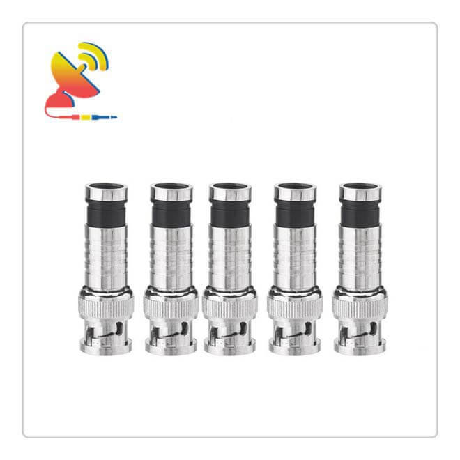
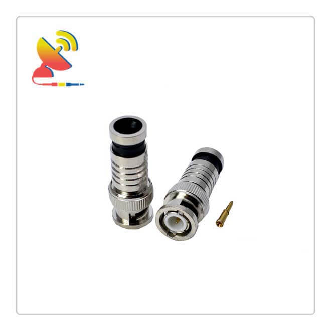
The 75-5 RG59 BNC Compression Connector RG6 Cable Q9 Connector CTRF-ANTENNA-C-F-COMP RF coaxial cable compression connector is a BNC compression connector RG59 coaxial cable BNC male connector solder-free style connector RG 6 cable Q9 connector supplied by C&T RF Antennas Inc.
75-5 RG59 BNC Compression Connector RG6 Cable Q9 Connector Product Description
[Name]: RG59 BNC Compression Connector (extrusion) BNC / Q9 connector solder-free for RG60 Cable
【Material】: The main body of the RG59 BNC Compression Connector is brass nickel-plated, conductor pure copper gold-plated
Specifications: RG59 BNC Compression Connector Length: 3.85 cm, 3.35 cm after compression, standard BNC / Q9 interface, suitable for 75-5 / RG59 & RG60 diameter 6.8 mm or so wire, another -4 and -3 are optional
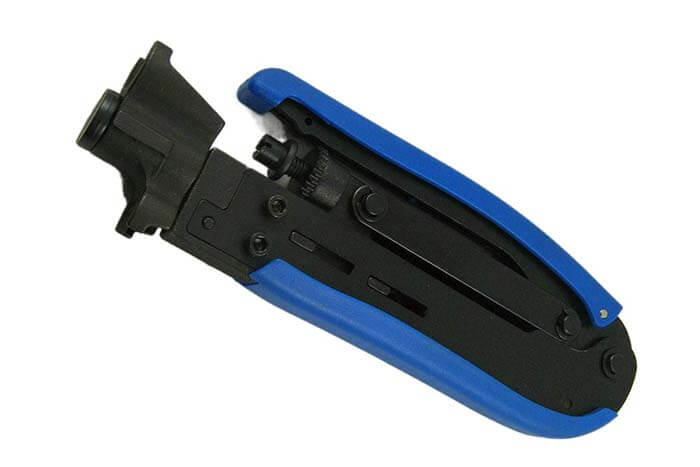
[Use]: You need to use the squeeze clamp to connect the RG59 BNC compression connector with the coaxial cable
【Features】: Waterproof, anti-shedding, suitable for outdoor construction, easy to make without welding, save time and effort, solid electrical performance is the best, the best design on the market
【Notes】: The RG59 BNC compression connector color of the plastic parts at the end of the product is due to the manufacturer’s batch, there will be different colors, does not affect the use of the default randomly sent, do not accept the specified color.
What is a BNC terminator?
A BNC terminator is used to prevent the signal from reaching the cable break and reflecting back to produce interference. A terminator is a special connector that has a carefully selected internal resistor matching the characteristics of the network cable.
Each BNC terminator must be grounded.
What is a BNC connector?
BNC connector, a connector for coaxial cables, is known as Bayonet Nut Connector (bayonet nut connector, a name that graphically describes the shape of this connector), also known as British Naval Connector (probably the first British Navy to use this connector) or Bayonet Neill Counselman (the connector was invented by a man named Neill Counselman).
First of all, we should know that there are usually two types of BNC: one for 50 ohms and one for 75 ohms.
In general: communication reception (small signal) often uses 75 ohms; communication transmission (high power) is 50 ohms. The monitoring system video signal belongs to the former, so the use of 75-ohm impedance.
Under the same specifications (such as both -7 or -5 or -3) the insulation of the core is the same diameter, but the diameter of the central conductor is different: 50 ohms is thicker than 75 ohms.
For sockets: the diameter of the center conductor of 50 ohms is larger than that of 75 ohms, which means that the hole of 75 ohms is smaller.
For plugs: the diameter of the center conductor of 50 ohms is larger than that of 75 ohms, which means that the core of 75 ohms is thinner.
So if the plug and socket impedance mismatch, in addition to increased insertion loss, also causes poor contact (such as a 50-ohm seat with a 75-ohm plug), or vice versa, causing the insertion of too tight (such as a 75-ohm seat to use 50-ohm plug).
BNC Connector Classification
Classification: BNC is divided into solder type and solder-free type
Solder-type BNC connector
Solder type as the name implies is fixed with soldering iron and solder, this is currently the more common form of domestic use. Solder can be classified according to the shape of the British and American two; the material can be divided into the core, zinc alloy, and copper.
Solder-free type BNC connector
Solder-free is divided into two kinds: one is the screw twist, which is the middle axis wiring with a screw, for quick connection, the disadvantage is easy oxidation after poor contact, the advantage is that the requirements of the cable are not high, the domestic specifications of the cable are relatively uneven, so the domestic welding-free products are also more common.
The other three are higher requirements for the cable, generally more foreign use, respectively, are straight screw, cold pressed, and extrusion type.
The straight twist is no crimping tool, the coaxial cable in accordance with a certain length of stripped wire, by rotating clockwise into it can be fixed and has good contact, the advantage is easy to install and use, the disadvantage is that the cable requires standard specifications;
Cold compression is through special cold crimping pliers crimping, and crimping crystal head similar to the advantages of this method of connection is good contact, convenience and fast, is the fastest way to connect large quantities, is also more reliable and durable, the disadvantage is that the cable requirements specifications standard.
Squeeze type crimp effect is similar to the straight screw type, but the water resistance after the pull is stronger and more suitable for harsh environment use.
Making crimped RG59 BNC Compression Connectors requires special BNC compression tools such as crimping tool wire pliers and a compression connector electrician’s knife.
C&T RF Antennas Inc provides RF Antenna Accessories such as Amplifiers And Repeaters, Connectors And Adapters, Cable Assemblies, etc.
C&T RF Antennas Inc also provides the RF antenna with many radio frequencies such as 169MHz, 230MHz, 315MHz, 433MHz, 868MHz, 915MHz, VHF&UHF, Lora, NB-IoT, ADS-B, GSM, GNSS, Wifi 2.4GHz, 5.8GHz, 2G 3G 4G LTE, GPS, 5G NR, etc.
C&T RF Antennas Inc provides the indoor-outdoor antenna with many antenna types such as Dipole Antennas, Whip Antennas, Marine Antennas, Router Antennas, MIMO Antennas, PCB Antennas, FPC Antennas, Spring Antennas, etc.
Contact us for more details on the 75-5 RG59 BNC Compression Connector RG6 Cable Q9 Connector such as the RG59 BNC Compression Connector datasheet, RG59 BNC Compression Connector pricing, and RG59 BNC Compression Connector inventory.
Note: This is a compression type connector RG59 BNC Compression Connector, you need to use the compression crimper extrusion pliers to use, please read the instructions carefully, so as not to buy the wrong!
How to solder a BNC compression connector?
The specific methods are as follows.
1. Strip the cable
The coaxial cable is made up of a protective rubber skin, a metal shielding mesh (grounding shield), a milky white transparent insulation layer, and a core wire (signal wire) from the outside to the inside, the core wire is made up of one or several copper wires, the metal shielding mesh is a metal net woven by metal wires, the inner and outer wires are filled with a milky white transparent insulation, the inner and outer wires are kept coaxially solid called coaxial cable.
Strip the wire with a knife to peel off 1.5cm of the outer protective rubber of the coaxial cable, being careful not to cut the metal shield wire, and then peel off 0.6cm of the milky white transparent insulation outside the core wire, so that the core wire is bare.
2. Connect the core wire
The purchased BNC connector consists of a BNC connector body, shielding metal sleeve, and core pin in three pieces, the core pin is used to connect the coaxial cable core; peel the line, and please insert the core into the core pin tail of the small hole, use the small slot in the front of the special card wire pliers to clamp hard, so that the core is pressed in the small hole.
You can use a soldering iron to solder the core wire and core wire pins, solder the core wire pins in the small hole at the end of the placement of a little rosin powder or neutral flux solder, soldering, and take care not to solder flow in the outer surface of the core wire pins, will lead to the core wire pins scrap.
Note: If you do not have special card wire pliers can be used instead of electrician pliers, but need to pay attention to one not to make the core pin deformation too large, the second is the core wire pressure to prevent poor contact.
3. Assembly BNC connector
After connecting the core wire, first put the shielding metal sleeve into the coaxial cable, then insert the core wire pin from the tail hole of the BNC connector body forward, so that the core wire pin extends outward from the front, and finally push the metal sleeve forward so that the sleeve will be the outer metal shielding wire stuck in the cylinder at the end of the BNC connector body;
4. Crimp the wire
Keep the sleeve in good contact with the metal shield wire, and use the hexagonal jaws on the wire clamp to clamp it hard so that the sleeve is shaped into a hexagonal shape.
Repeat the above method to make a BNC connector at the other end of the coaxial cable that is finished. It is best to check it with a multimeter before use. A broken circuit or short circuit will lead to no communication and may damage the network card or hub.
Note: To make assembled BNC connectors, use a small screwdriver and electrician’s pliers. After stripping the wires as described above, insert the core wire into the core wire fixing hole, then use a small screwdriver to fix the core wire, twist the outer metal shield wire together, fix it in the shield wire fixing sleeve with an electrician’s pliers, and finally screw the tail metal on the BNC connector body.
To make a soldering type BNC connector needs to use an electric soldering iron, after stripping the wire according to the aforementioned method, only need to use an electric soldering iron to solder the core wire and shield wire on the soldering point of the BNC connector head set hard long material insulation sleeve and soft long material tail sleeve.
How to Wire When Installing Video Surveillance BNC Compression Connector for CCTV Camera RG59 Coax Cables?
1. Different construction environment has different requirements
2. It is better not to have joints in the video cable
3. If there is a moving point, the control line is better to reduce the star node
4. There are strong points of equipment, according to the strong voltage to maintain a certain distance (see national standards)
5. Power lines are calculated after the size of the current, choose the right line through, and try to save wiring
6. According to the environmental situation, with the appropriate line pipe

Reviews
There are no reviews yet.