Description
What is 8-Way RF Power Divider?
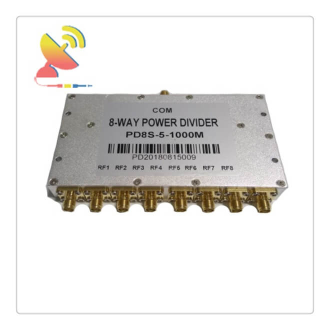
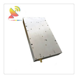
The 8-Way RF Power Divider CTRF-ANTENA-PSPD-5-1000-8W 8-Way Power Splitter 5-1000MHz RF Power Divider has an 8-way reactive power divider that operates from 0.35 to 6 GHz supplied by C&T RF Antennas Inc.
Besides the 5-1000MHz RF Power Divider, C&T RF Antennas Inc also provides the 5-1000MHz 16 Way Power Divider for your best choice.
8-Way RF Power Divider is supplied by C&T RF Antennas Inc, we provide RF products with RF antennas, Antenna Accessories, Amplifiers, And Repeaters.
C&T RF Antennas Inc provides internal & external antennas with antenna radio frequencies such as NFC, 169MHz, 230MHz, 315MHz, 433MHz, 868MHz, 915MHz, VHF&UHF, Lora, NB-IoT, ADS-B, GSM, GNSS, GPRS, 1.2 GHz, 1.4 GHz, 1.8 GHz, Wi-Fi 2.4 GHz, 5.8 GHz, Cellular 2G, 3G, 3.5 GHz, 4G LTE, GPS, 5G NR, 6G, etc.
C&T RF Antennas Inc. provides RF antennae with Omni & Directional antenna types such as Dipole Antennas, Whip Antennas, Marine Antennas, Router Antennas, MIMO Antennas, Combo Antennas, PCB Antennas, FPC Antennas, Spring Antennas, Magnetic Antennas, Sector Antennas, Yagi Antennas, and Accessories, etc, for IoT & M2M industries.
8-Way Power Splitter 5-1000MHz RF Power Divider Is Available At C&T RF Antennas Inc. We offer the RF Power Divider Inventory, RF Power Divider Pricing, and RF Power Divider Datasheets For The 8-Way Power Splitter or other Splitters.
RF Power Divider Specifications:
| Product Type | 8-Way RF Power Divider |
| Frequency(MHz) | 5-1000 |
| Insertion Loss(Max) | ≤3.2dB (Excluding theoretical loss of 9.03 dB) |
| Isolation | ≥20dB |
| Connector | SMA Female |
| Power Rating | 5 Watt |
| Amplitude Balance dB(Max) | ±0.3 |
| Impedance(ohm) | 50 |
| VSWR | ≤1.5:1 |
| Working Temperature | -30~+70 degree |
| Storage Temperature | -40 to +70 degree |
| Operating Humidity | 0 to 90%, relative |
| Phase Balance | ±8° |
| Color | Aluminum |
RF Power Divider / RF Power Splitter / RF Power Combiner
Passive RF splitters/dividers and combiners are just the reverse of each other – they are just used the other way round.
RF Combiner Splitter Coupler Includes:
Splitters & Combiners
Directional coupler
As the name implies RF power splitters/dividers and combiners are used to split a single RF line into more than one line and divide the power, and similarly combiners are used to combine more than one feed line into a single one.
RF power combiners and RF splitters are the same items. The same circuits can be used to combine and split RF power, the only difference being that RF power is applied to one port and extracted from others in the case of the RF splitter, and for the RF combiner, power is applied in the opposite direction.
Typical microwave connectors splitter/combiner
Typical commercially available microwave splitter/divider
RF power splitter & combiner types
There are two broad categories of RF splitters:
Resistive power splitters:
As the name implies, these power splitters and combiners use resistors. While they are able to maintain the characteristic impedance of the system, the use of resistors introduces loss above that of the minimum caused by any splitting action. They are cheap and easy to make.
Hybrid power splitters:
Hybrid splitters use transformers and are able to provide low levels of loss. Although there are some physical losses in the transformer, the major loss arises from the splitting process as the same signal is shared between a number of outputs.
Splitter and combiner symbols
A variety of circuit symbols may be used for splitters or dividers and combiners. They are typically quite self-explanatory, and may even have a function description on the symbol.
Splitter/power divider circuit symbol
Splitter / divide symbol
Where there is a requirement for splitting the power into more than two ways, the following symbol may be used.
n way splitter/power divider circuit symbol
n-way splitter/divide symbol
The combiner symbol is just the reverse of the splitter symbol.
Power combiner circuit symbol
Combiner symbol
Power splitter insertion loss
When a splitter is inserted into a circuit, there are naturally some losses resulting from the fact that no component is perfectly lossless. These losses are generally minimized and cannot be calculated exactly.
Typical microwave connectors 8-way splitter/combiner
Typical commercially available microwave 8-way splitter/divider
However, there are also losses resulting from the fact that the signal is divided between several outputs. This should more accurately be described as a division signal reduction as none of the signals is actually lost. Instead, there is a level reduction from the fact that the input power is being shared amongst several outputs.

Reviews
There are no reviews yet.