RF circuit design is now more important than ever as we find ourselves in an increasingly wireless world. Radio is the backbone of today’s wireless industry with protocols such as Bluetooth, Wi-Fi, WiMax, and ZigBee.
What is an RF circuit?
RF for short, RF is a radio frequency current, it is a high-frequency alternating current electromagnetic wave short.
The alternating current that changes less than a thousand times per second is called low-frequency current, more than a thousand times is called high-frequency current, and RF is such a high-frequency current.
RF circuit refers to the circuit in which the electromagnetic wavelength of the processed signal is in the same order of magnitude as the circuit or device size. In this case, due to the relationship between device size and wire size, the circuit needs to be handled with the theory related to the distribution parameters.
These types of circuits can all be considered RF circuits, which do not have strict requirements for their frequency, such as the long-distance transmission of AC transmission lines, and sometimes have to be treated with the relevant theory of RF.
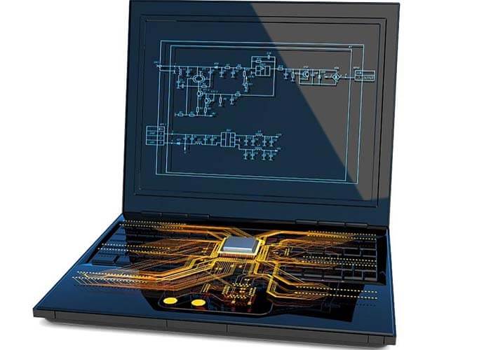
This system model of a wireless communication transceiver contains a transmitter circuit, a receiver circuit, and a communication antenna. This transceiver can be used in personal communications and wireless local area networks.
In this system, the digital processing part is mainly to process the digital signal, including sampling, compression, coding, etc.; then it is turned into analog form into the analog signal circuit unit through the AD converter.
How to layout the RF circuit
As far as possible to isolate the high power RF amplifier and low noise amplifier, simply put, is to keep the high power RF transmitter circuit away from the low power RF receiver circuit
Ensure that the PCB board on the high power area of at least one block of land, the best above no over-hole, of course, the larger the copper foil area the better.
Circuit and power decoupling are also extremely important.
RF output usually needs to be away from the RF input.
Sensitive analog signals should be as far away as possible from high-speed digital signals and RF signals.
RF circuit principles
RF circuit principle is divided into three parts, the first is the structure and working principle of the receiver circuit, then the structure and working principle of the transmitter circuit, and finally the structure and working principle of the local oscillator circuit.
When receiving, the antenna converts the electromagnetic wave sent from the base station into a weak AC signal after filtering and high-frequency amplification, and then sends it to the IF for demodulation to get the received baseband information. Send to the logic audio circuit for further processing.
Circuit structure
The receiving circuit consists of an antenna, antenna switch, filter, high amplifier tube, IF integrated block, and other circuits. Early cell phones have primary and secondary mixing circuits, whose purpose is to reduce the received frequency before demodulation.
When transmitting, the logic circuit is processed by the transmitting baseband information modulated into the transmitting IF, the transmitting IF signal frequency into the GSM frequency signal. After amplification by the amplifier, it is converted into electromagnetic wave radiation by the antenna.
Circuit structure
The transmitting circuit consists of the transmitting modulator and transmitting discriminator inside the IF; the transmitting voltage controlled oscillator, power amplifier, power controller, transmitting transformer, and other circuits.
The local oscillator circuit generates four bands of local oscillation frequency signal without any information; it is sent to the internal IF, and when receiving, the received signal is demodulated; when transmitting, the transmitting baseband information is modulated and the transmitting phase discriminator is performed.
There are four circuit structures of the cell phone’s local oscillation circuit.
It consists of a frequency synthesis integrated block, receives voltage-controlled oscillator, reference clock, and preset frequency reference data.
The frequency synthesis integrated block is integrated inside the IF, combined with an external, receive voltage-controlled oscillator.
The frequency synthesis integrated block, receives voltage controlled oscillator integrated, called the local oscillation integrated block or local oscillation licking IC.
The frequency synthesis integrated block, receives a voltage control oscillator integrated into the internal IF.
It is worth noting that no matter what structure mode is used, only the generated frequency is different; its working principle, the direction of the generated frequency signal, and the role are the same.
RF circuit applications
RF circuit design application areas are ETC, railroad locomotive vehicle identification tracking, container identification, access control management, animal identification, tracking, automatic vehicle locking, etc.
RF circuit design guide
Four aspects teach you how to design RF circuits.
RF circuit simulation of the interface of RF, RF circuit simulation of the large interference signal, RF circuit simulation of the small expected signal, RF circuit simulation of the interference of adjacent channels.
Wireless transmitter and receiver can be conceptually divided into two parts: fundamental frequency and RF.
The fundamental frequency contains the frequency range of the input signal of the transmitter and the frequency range of the output signal of the receiver. The bandwidth of the fundamental frequency determines the basic rate at which data can flow in the system. The fundamental frequency is used to improve the data flow’s reliability and reduce the load imposed by the transmitter on the transmission medium at a given data rate.
Therefore, PCB design of the fundamental frequency circuit requires extensive knowledge of signal processing engineering.
The transmitter’s RF circuitry converts and upscales the processed fundamental frequency signal to a specified channel and injects this signal into the transmission medium. Conversely, the receiver’s RF circuitry can obtain signals from the transmission media and convert and downconvert them to fundamental frequencies.
Transmitters have two main PCB design goals
The first is that they must transmit a specific amount of power while consuming the least amount of power possible. The second is that they must not interfere with the normal operation of the transceiver in adjacent channels.
Receivers have three main PCB design goals
First, they must accurately restore small signals; second, they must be able to remove interference signals outside the desired channel; the last point is the same as the transmitter, they must consume very little power.
Receivers must be sensitive to small signals, even when large interfering signals are present. This situation arises when trying to receive a weak or distant transmitting signal with a powerful transmitter broadcasting in an adjacent channel nearby.
The interference signal may be larger than the expected signal of sixty to seventy decibels and can be in the input phase of the receiver in a large number of ways to cover or make the receiver in the input phase generate excessive amounts of noise to block the reception of normal signals.
If the receiver in the input stage, driven into the region of non-linearity by the source of interference, the above-mentioned two problems will occur. To avoid these problems, the front end of the receiver must be very linear.
Therefore, linearity is also an important consideration when designing a receiver for PCB. Since the receiver is a narrow-frequency circuit, nonlinearity is measured in terms of cross-tuning distortion to statistics. This involves using two sine waves or, cosine waves of similar frequency and located in the center frequency band to drive the input signal, and then measuring the product of its cross-modulation.
Distortion also plays an important role in the transmitter
The nonlinearity created by the transmitter in the output circuit may cause the bandwidth of the transmitted signal to spread across adjacent channels. This phenomenon is called spectral re-growth. Before the signal reaches the transmitter’s power amplifier, its bandwidth is limited; however, cross-modulation distortion in the power amplifier causes the bandwidth to increase again.
If the bandwidth increases too much, the transmitter will not be able to meet the power requirements of its adjacent channels. When transmitting a digital modulation signal, it is practically impossible to predict the re-growth of the spectrum with spice.
Because there are about 1000 digital symbols that must be simulated to obtain a representative spectrum and need to be combined with high-frequency carriers, these will make the transient analysis of spice impractical.
The receiver must be very sensitive to detect small input signals. The sensitivity of the receiver is limited by the noise generated by its input circuitry. Therefore, noise is an important consideration when designing a receiver for PCB. Moreover, having the ability to predict noise with simulation tools is essential.
Common problems in RF circuit design
Interference between digital circuit modules and analog circuit modules
If analog and digital circuits work separately, they may each work well. However, once the two are placed on the same board and work together using the same power supply, the whole system is likely to be unstable.
This is mainly because the digital signal frequently oscillates between ground and positive power supply, and the period is particularly short, often in nanoseconds. Due to the large amplitude and short switching time so that these digital signals contain a large and independent of the switching frequency of the high-frequency components.
In the analog part, from the wireless tuning loop to the wireless device receiving part of the signal is generally less than 1. Therefore, the difference between the digital signal and the RF signal will reach one hundred and twenty decibels.
Obviously, if you can not make the digital signal and RF signal well separated. A weak RF signal may be damaged, so that the wireless device work performance will deteriorate, or even completely unable to work.
Noise interference of the power supply
RF circuits are quite sensitive to power supply noise, especially to burr voltages and other high-frequency harmonics. The microcontroller will suddenly draw most of the current for a short time during each internal clock cycle, which is because modern microcontrollers are manufactured using the C mos process.
Therefore. Assuming a microcontroller runs at an internal clock frequency of one megahertz, it will draw current from the power supply at this frequency. If proper power supply decoupling is not taken. Voltage burrs on the power supply lines will be caused. If these voltage burrs reach the power supply pins in the RF portion of the circuit, they can cause severe operational failure.
Unreasonable ground
If the RF circuit ground is not handled properly, it may produce some strange phenomena. For digital circuit designs, most digital circuits function well even without a ground layer. And in the RF band, even a very short ground wire will act as an inductor. Without a ground layer, most ground lines would be longer and the circuit would not have the characteristics it was designed for.
Radiation interference from the antenna to other analog circuit parts
In the PCB circuit design, there are usually other analog circuits on the board. For example, many circuits have analog-to-digital converters or digital-to-analog converters on them. If the analog-to-digital converter input is not handled properly, RF signals may self-excite within the electrostatic protection diode of the converter input.
This causes converter bias.
Besides the RF circuit design article, You may also be interested in the below articles.
What is the difference between WIFI and WLAN?
Summary of 41 Basic Knowledge of LTE
What Is The 5G Network Slicing?