
Description
What is a 5G NR 600-6000MHz UWB Ultra-wideband PCB Antenna Log Periodic Antenna?
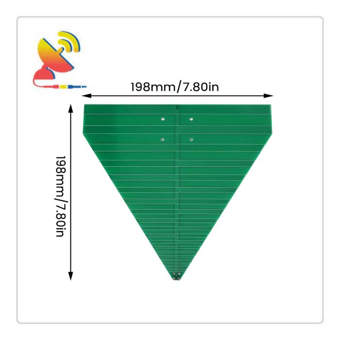
The 600-6000MHz UWB antenna CTRF-ANTENNA-PCB-60600-200200-SMA item is a UWB antenna PCB Log Periodic Antenna with an Ultra-wideband frequency 600MHz to 6000MHz PCB Antenna Log Periodic Antenna, it comes with a 20x20cm PCB board size and SMA female connector antenna manufactured by C&T RF Antennas Inc.
5G NR 600-6000MHz UWB Ultra-wideband PCB Antenna Log Periodic Antenna Is Available At C&T RF Antennas Inc. The leading ultra-wideband antenna UWB antenna manufacturer in China.
C&T RF Antennas Inc provides internal & external antennas with antenna radio frequencies such as NFC, 169MHz, 230MHz, 315MHz, 433MHz, 868MHz, 915MHz, VHF&UHF, Lora, NB-IoT, ADS-B, GSM, GNSS, GPRS, 1.2 GHz, 1.4 GHz, 1.8 GHz, Wi-Fi 2.4 GHz, 5.8 GHz, Cellular 2G, 3G, 3.5 GHz, 4G LTE, GPS, 5G NR, 6G, etc.
C&T RF Antennas Inc. provides RF antennae with Omni & Directional antenna types such as Dipole Antennas, Whip Antennas, Marine Antennas, Router Antennas, MIMO Antennas, Combo Antennas, PCB Antennas, FPC Antennas, Spring Antennas, Magnetic Antennas, Sector Antennas, Yagi Antennas, and Accessories, etc, for IoT & M2M industries.
Contact Us For More Info On Log Periodic Antenna PCBs, such as Log Periodic Antenna datasheets, pricing, and inventory.
5G NR 600-6000MHz UWB Ultra-wideband PCB Antenna Log Periodic Antenna Specifications
5G NR 600-6000MHz UWB Ultra-wideband PCB Antenna Log Periodic Antenna Electrical Specifications |
|
| RF Antenna Type | PCB Antenna |
| Model | CTRF-ANTENNA-PCB-60600-200200-SMA |
| Frequency | 600MHz-6000MHz |
| Gain | 3/6dBi |
| VSWR | ≤3.0 |
| Impedance | 50 Ω |
| Polarization | Vertical/linear |
| Connector | SMA Female |
| Lightning Protection | DC-Ground |
5G NR 600-6000MHz UWB Ultra-wideband PCB Antenna Log Periodic Antenna Mechanical Specifications |
|
| PCB Board Dimension | 20*20cm |
| Weight | Approx. 10g |
| Material | PCB Board |
| Operation Temperature | -40˚C ~ +75˚C |
| Storage Temperature | -40˚C ~ +80˚C |
| Color | Green |
| Antenna Design | Dipole Antenna |
| Mounting | Screw |
| Safety, Emission, and other | RoHS Compliant |
600-6000MHz 5G NR UWB Ultra-wideband PCB Antenna Log Periodic Antenna Drawing
Is it Ultra Wide Band (UWB)?
The relative energy bandwidth of the electromagnetic wavewaveform is greater than 0.2~0.25.
Understanding of waveform energy bandwidth?
Determined by the frequency FL and FH, if most of the energy of the waveform (greater than 90%, that is, -10dB radiation point, here -10DB means that the waveform energy 0DB drops to -10DB, and the energy drops from 1 to 0.1 energy. 0.9 energy, 0.1 energy left).
Definition: FH-FL
Upper and lower limit frequency FL and FH?
Definition: The latest UWB energy radiation standard released by the United States [FCC, 2002] defines the offline frequency FL and the upper limit frequency FH at the radiation point where the power spectral density is attenuated to -10DB.
What is an ultra-wideband signal (UWB signal)?
(1) The energy bandwidth of a signal is greater than one-fifth of the center frequency.
(2) Because the signal relative bandwidth = signal bandwidth/center frequency.
If the -10DB radiation point bandwidth in the signal energy (power) spectral density graph is greater than 500M, that is, 500M/center frequency=0,2, that is, the center frequency is 2.5GHz, and the signal can be roughly regarded as a UWB signal. (From the lower bandwidth of 500Mhz, a threshold of 2.5Ghz is obtained.)
Definition:
(1) The relative bandwidth of a signal is greater than 0.2~0.25.
(2) The bandwidth of the -10DB radiation point of a signal has exceeded 500MHz. Regardless of the relative bandwidth of the signal, it can be regarded as a UWB signal.
What is relative bandwidth?
The energy bandwidth of a signal is the percentage of the center frequency.
Definition: The ratio of the signal energy bandwidth to the center frequency.Signal energy (power) spectral density-frequency diagram?
Indicate the relationship between signal energy and frequency.
How to generate a UWB signal?
Since UWB signals are only defined from the frequency domain perspective (relative bandwidth/minimum bandwidth), there are many ways to generate UWB signals:
Impulse plan:
IR-UWB (Impulse Radio UWB)-Narrow Pulse
(1). Coding of data symbols (applying pseudo-random code or pseudo-random noise (PN) to encode information data symbols)
–The purpose is to form the required spectrum
A. TH-UWB (Time-Hopping UWB)
B. DS-UWB (direct sequence ultra-wideband). In the case of non-IR, this modulation is called DS-SS direct sequence spread spectrum)
C. MB (multi-band)
D. Frequency-hopping spread spectrum
(2). Data modulation-pulse modulation (modulate the pulse with information data symbols)
A. PPM pulse position modulation
B. PAM pulse amplitude modulation
Non-impulse solution:
OFDM (Orthogonal Frequency Division Multiplexing)
MC-CDMA (Multi-Carrier Code Division Multiple Access)
Note: DS-SS OFDM MC-CDMA usually operates at radio frequency (baseband signal modulates the carrier), whereas UWB typically uses baseband operation. Therefore, radio-frequency modulation is rarely mentioned in UWB systems (RF modulation can also be used for UWB; frequency changes are achieved through pulse formation).
Reviews
There are no reviews yet.