Description
What is a PCB Trace Antenna LTE 3G 4G Antenna?
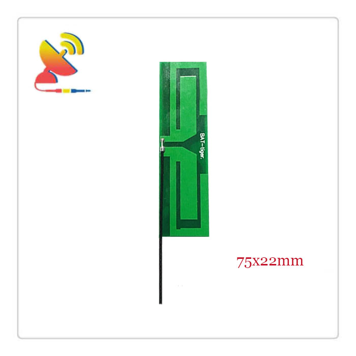
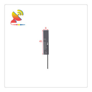
The PCB Trace Antenna LTE 3G 4G Antenna item CTRF-ANTENNA-PCB-7027-7522-IPEX is an embedded PCB trace antenna with 2G 3G 4G full-band LTE PCB antenna manufactured by C&T RF Antennas Inc., a leasing RF antenna manufacturer in China.
NB-IoT products are an interesting area of development right now, with many new applications in remote-controlled lighting, tracking, and wearable electronics. However, the greatest demand is for smaller products, which means the devices must work with shorter ground planes and cannot use too much power.
It comes with a 4dBi/6dBi high-gain, 698- 960MHz, 1710- 2700MHz 4G frequency, 4G network antenna used in IoT M2M and NB-IoT application products.
C&T RF Antennas Inc provides internal & external antennas with antenna radio frequencies such as NFC, 169MHz, 230MHz, 315MHz, 433MHz, 868MHz, 915MHz, VHF&UHF, Lora, NB-IoT, ADS-B, GSM, GNSS, GPRS, 1.2 GHz, 1.4 GHz, 1.8 GHz, Wi-Fi 2.4 GHz, 5.8 GHz, Cellular 2G, 3G, 3.5 GHz, 4G LTE, GPS, 5G NR, 6G, etc.
C&T RF Antennas Inc. provides RF antennae with Omni & Directional antenna types such as Dipole Antennas, Whip Antennas, Marine Antennas, Router Antennas, MIMO Antennas, Combo Antennas, PCB Antennas, FPC Antennas, Spring Antennas, Magnetic Antennas, Sector Antennas, Yagi Antennas, and Accessories, etc, for IoT & M2M industries.
Contact us for the PCB Trace Antenna LTE 3G 4G Antenna for more details, such as LTE 3G 4G Antenna datasheet, LTE 3G 4G Antenna pricing, LTE 3G 4G Antenna inventory, or other LTE 3G 4G Antenna PCB Antenna types.
PCB Trace LTE 3G 4G Antenna Specifications:
PCB Trace LTE 3G 4G Antenna Electrical Specifications |
|
| RF Antenna Type | Built-in PCB Antenna |
| Model | CTRF-ANTENNA-PCB-7027-7522-IPEX |
| Frequency | 698-960MHz, 1710-2700MHz |
| Gain | 5dBi/7dBi |
| VSWR | ≤2 |
| Impedance | 50 Ω |
| Polarization | Vertical/Linear |
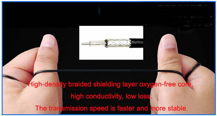
| Cable Type | RG1.13 |
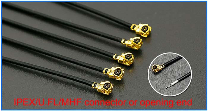
| Connector | U.FL/IPEX |
| Cable Length | 100mm |
| Lightning Protection | DC-Ground |
PCB Trace LTE 3G 4G Antenna Mechanical Specifications |
|
| PCB Board Dimension | 75*22mm |
| Weight | Approx. 5g |
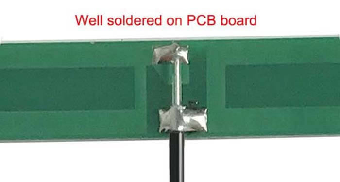
| Material | PCB + RG Cable + U.FL connector |
| Operation Temperature | -40˚C ~ +65˚C |
| Storage Temperature | -40˚C ~ +70˚C |
| Color | Green |
| Antenna Design | Dipole Antenna |
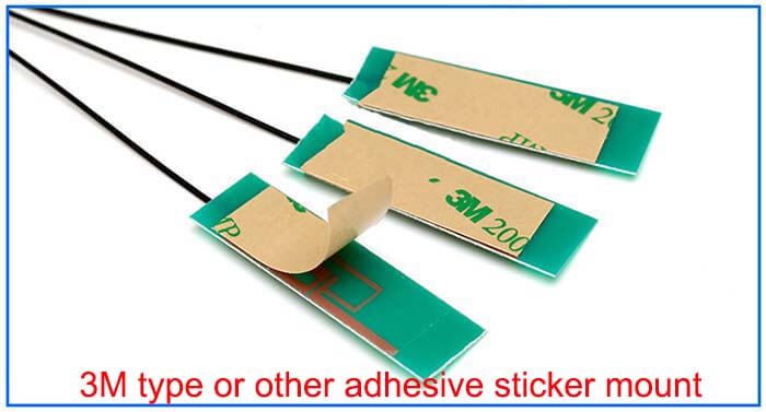
| Mounting | Connector/Peel-and-stick |
| Safety, Emission, and other | RoHS Compliant |
| Applications | ISM/SCADA/Utilities, IoT/M2M/NB-IoT/LoRa, 2G 3G 4G LTE/LTE-IoT, GSM GPRS UMTS, etc. |
LTE 3G 4G Antenna PCB Antenna Features
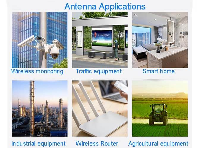
LTE 3G 4G Antenna Applications
Antenna Isolation Design Requirements
1. Antenna Isolation
For two or more antennas with overlapping frequency bands in space, antenna isolation is defined as the ratio of a signal received by one antenna to the signal transmitted by another antenna. The isolation depends on the radiation pattern of the antenna, the spatial distance of the antennas, etc.
Antenna isolation improvement is to take measures to minimize the impact of various interference on the receiver.
The isolation between antennas can be increased by:
⚫ Increasing the physical separation between the antennas
⚫ Placing antennas working in adjacent bands orthogonally to each other
⚫ Having the antenna’s peak radiation in different or opposite directions
⚫ Changing the antenna trace implementation method (such as length, width)
Additionally, adding a filter in the RF signal path will help to improve the desired signals’ suppression effect on those unwanted signals, thus abating the interference caused by insufficient antenna isolation.
2. Isolation between 3G/4G Antenna and GNSS Antenna
⚫ The isolation between a 3G/4G antenna and a GNSS active antenna should be at least 10dB.
⚫ The isolation between a 3G/4G antenna and a GNSS passive antenna should be at least 15 dB.
It is recommended to add a filter between a GNSS antenna and a module to suppress interference from other antennas.
3. Isolation Design of Other Antennas
⚫ The isolation of other antennas should be at least 15 dB.
⚫ Isolation design is vital to antennas working at similar frequencies. When two antennas are used synchronously, one of them is recommended to be designed to support only part of the bands to ensure better performance.
For example, for a device supporting GSM B1/B3/B5/B8 & LTE B1/B3/B7, the main antenna should support all the bands while the diversity antenna only needs to support LTE bands.

Reviews
There are no reviews yet.