Description
What is an Omni-Directional 4G LTE Antenna PCB Antenna?
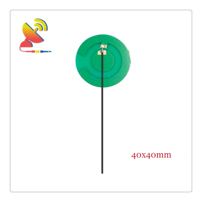
This is the round shape Omni-Directional 4G LTE Antenna PCB Antenna CTRF-ANTENNA-PCB-7027-4040-IPEX that comes with a 40x40mm PCB trace board antenna design supplied by C&T RF Antennas Inc for 4G LTE device network applications.
C&T RF Antennas Inc. is the Omni-Directional 4G LTE Antenna CTRF-ANTENNA-PCB-7027-4040-IPEX 4G LTE Antenna manufacturer of antennas and RF antenna modules for M2M and the Internet of Things antennas to cover the 2G, 3G, 4G, and LTE bands.
C&T RR Antennas Inc. is The Manufacturer Of Antennas And RF Antenna Modules For M2M IoT Antennas To Cover The 2G, 3G, 4G, GSM, GRPS, PCS, NB-IoT, Lora, And LTE Cellular Bands.
C&T RF Antennas Inc provides internal & external antennas with antenna radio frequencies such as NFC, 169MHz, 230MHz, 315MHz, 433MHz, 868MHz, 915MHz, VHF&UHF, Lora, NB-IoT, ADS-B, GSM, GNSS, GPRS, 1.2 GHz, 1.4 GHz, 1.8 GHz, Wi-Fi 2.4 GHz, 5.8 GHz, Cellular 2G, 3G, 3.5 GHz, 4G LTE, GPS, 5G NR, 6G, etc.
C&T RF Antennas Inc. provides RF antennae with Omni & Directional antenna types such as Dipole Antennas, Whip Antennas, Marine Antennas, Router Antennas, MIMO Antennas, Combo Antennas, PCB Antennas, FPC Antennas, Spring Antennas, Magnetic Antennas, Sector Antennas, Yagi Antennas, and Accessories, etc, for IoT & M2M industries.
Contact us for the Omni-Directional 4G LTE Antenna PCB Antenna for more details, such as Omni-Directional 4G LTE Antenna PCB Antenna datasheet, Omni-Directional 4G LTE Antenna PCB Antenna pricing, and Omni-Directional 4G LTE Antenna PCB Antenna inventory, or other Omni-Directional 4G LTE Antenna types.
Omni-Directional 4G LTE Antenna Specifications:
Omni-Directional 4G LTE Antenna Electrical Specifications |
|
| RF Antenna Type | Built-in PCB Antenna |
| Model | CTRF-ANTENNA-PCB-7027-4040-IPEX |
| Frequency | 698-960MHz, 1710-2700MHz |
| Gain | 3/5dBi |
| VSWR | ≤2 |
| Impedance | 50 Ω |
| Polarization | Vertical/Linear |
| Cable Type | RG1.13 |
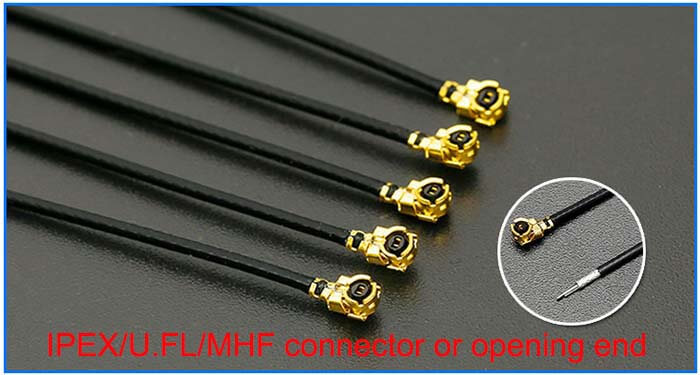
| Connector | U.FL/IPEX |
| Cable Length | 100mm |
| Lightning Protection | DC-Ground |
Omni-Directional 4G LTE Antenna Mechanical Specifications |
|
| PCB Board Dimension | 40*40mm |
| Weight | Approx. 3g |
| Material | PCB + RG Cable + U.FL connector |
| Operation Temperature | -40˚C ~ +65˚C |
| Storage Temperature | -40˚C ~ +70˚C |
| Color | Green |
| Antenna Design | Dipole Antenna |
| Mounting | Connector/Sticker |
| Safety, Emission, and other | RoHS Compliant |
| Applications | ISM/SCADA/Utilities, IoT/M2M/NB-IoT/LoRa, 2G 3G 4G LTE/LTE-IoT, GSM GPRS UMTS, etc. |
The 4G system is designed for a variety of different service access systems, connected to an IP-based core network through multimedia access.
The IP-based network structure allows users to roam seamlessly between 3G, 4G, WLAN, and fixed networks.
The 4G network structure can be divided into three layers: the physical network layer, the intermediate environment layer, and the application network layer.
1) The physical network layer provides access and routing functions.
2) The functions of the intermediate environment layer are network quality of service mapping, address transformation, and completeness management.
3) The interface between the physical network layer and the intermediate environment layer and its application environment is open, making it easier to develop and provide new services, providing seamless high data rate wireless services, and operating in multiple frequency bands, which can be adapted to multiple wireless standards and multi-mode terminals, across multiple operators and service providers to provide a wider range of
This service can be adapted to multiple wireless standards and multi-mode terminals, spanning multiple operators and service providers to provide a wider range of services.
Omni-Directional 4G LTE Antenna PCB Antenna Features
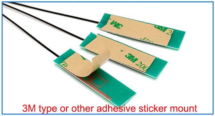
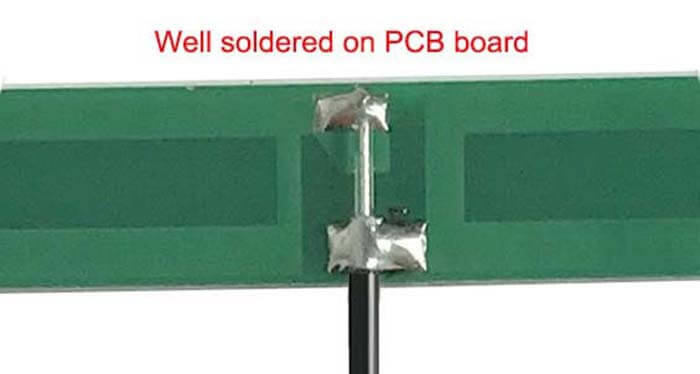
IPEX UFL MHF antenna connectors or opening end, -C&T RF Antennas Inc
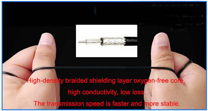
RG low-loss cable antenna extension antenna extender – C&T RF Antennas Inc
Omni-Directional 4G LTE Antenna Applications

PCB Antenna Design Notes:
1. It is suggested to keep the RF ports at the edge of the PCB and keep them away from the other circuits.
Avoid vias and layer changes when routing RF traces. RF traces should be designed to have an impedance of 50Ω. Please keep the distance between RF ports and antennas as short as possible.
If there is a long distance and it cannot be shortened anymore, it is recommended to use antenna cables for the antenna connection.
2. Please put antenna feed points at the edge of the main PCB, rather than in the center. For two antennas working at a similar frequency range, the distance between them should be more than a quarter-wavelength at the lowest frequency.
When the antennas are too close, they are recommended to be placed orthogonally to each other.
3. Generally speaking, the isolation between the antennas should be at least 10dB to avoid interference.

Reviews
There are no reviews yet.