Description
What is a 2.4 GHz Mini Wifi Antenna Indoor FPC Antenna?
The Wifi Antenna Indoor CTRF-ANTENNA-FPC-2450-2208-IPEX antenna item is a 2.4GHz antenna with an embedded antenna mini flexible Wi-Fi antenna manufactured by C&T RF Antennas Inc.
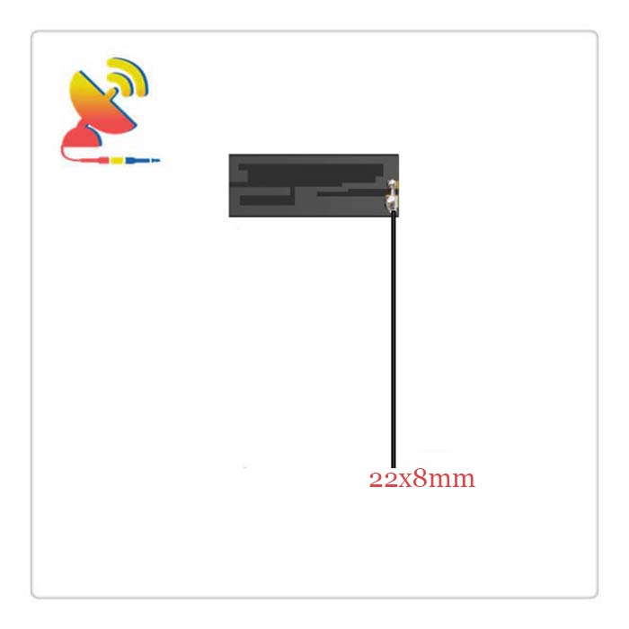
The Mini Wifi Antenna Indoor FPC Antenna is a mini Wi-Fi antenna with a 22x8mm flexible PCB circuit board mini size, self-adhesive double side sticker mount, and Ipex connector antenna for 2.4 GHz band wireless network smart devices.
C&T RF Antennas Inc provides internal & external antennas with antenna radio frequencies such as NFC, 169MHz, 230MHz, 315MHz, 433MHz, 868MHz, 915MHz, VHF&UHF, Lora, NB-IoT, ADS-B, GSM, GNSS, GPRS, 1.2 GHz, 1.4 GHz, 1.8 GHz, Wi-Fi 2.4 GHz, 5.8 GHz, Cellular 2G, 3G, 3.5 GHz, 4G LTE, GPS, 5G NR, 6G, etc.
C&T RF Antennas Inc. provides RF antennae with Omni & Directional antenna types such as Dipole Antennas, Whip Antennas, Marine Antennas, Router Antennas, MIMO Antennas, Combo Antennas, PCB Antennas, FPC Antennas, Spring Antennas, Magnetic Antennas, Sector Antennas, Yagi Antennas, and Accessories, etc, for IoT & M2M industries.
Contact us for the Mini Wifi Antenna Indoor FPC Antenna for more details such as Wifi Antenna Indoor Antenna datasheet, Wifi Antenna Indoor Antenna pricing, Wifi Antenna Indoor Antenna inventory, or other Mini Wifi Antenna Indoor FPC Antenna types.
2.4 Ghz Mini Wifi Antenna Indoor FPC Antenna Specifications:
2.4 GHz Mini Wifi Antenna Indoor FPC Antenna Electrical Specifications |
|
| RF Antenna Type | Embedded FPC Antenna |
| Model | CTRF-ANTENNA-FPC-2450-2208-IPEX |
| Frequency | 2400-2500 MHz |
| Gain | 2dBi |
| VSWR | ≤2.0 |
| Impedance | 50 Ω |
| Polarization | Vertical Polarization |
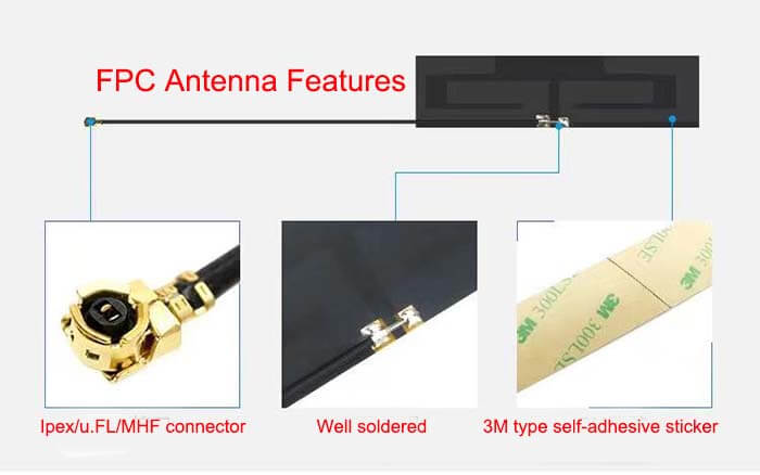
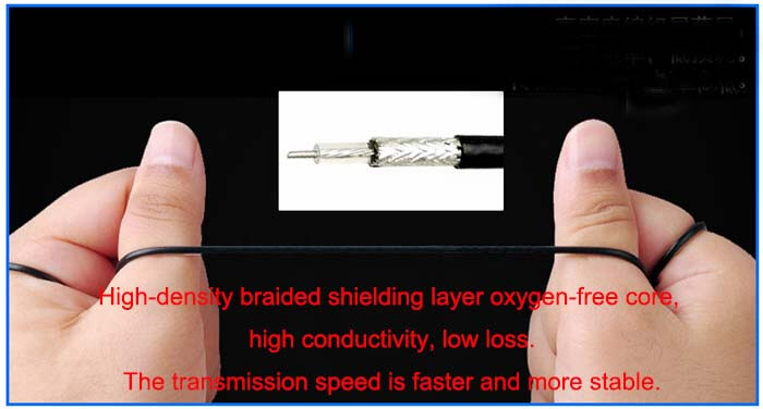
| Cable Type | RG1.13 |
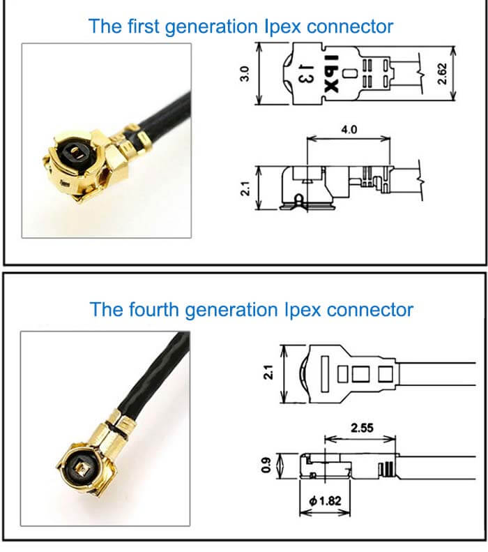
| Connector | U.FL/IPEX |
| Cable Length | 120mm |
| Lightning Protection | DC-Ground |
2.4 GHz Mini Wifi Antenna Indoor FPC Antenna Mechanical Specifications |
|
| FPC Board Dimension | 22*9mm |
| Weight | Approx. 3g |
| Material | FPCB + RG Cable + U.FL connector |
| Operation Temperature | -40˚C ~ +65˚C |
| Storage Temperature | -40˚C ~ +70˚C |
| Color | Black |
| Antenna Design | Dipole Antenna |
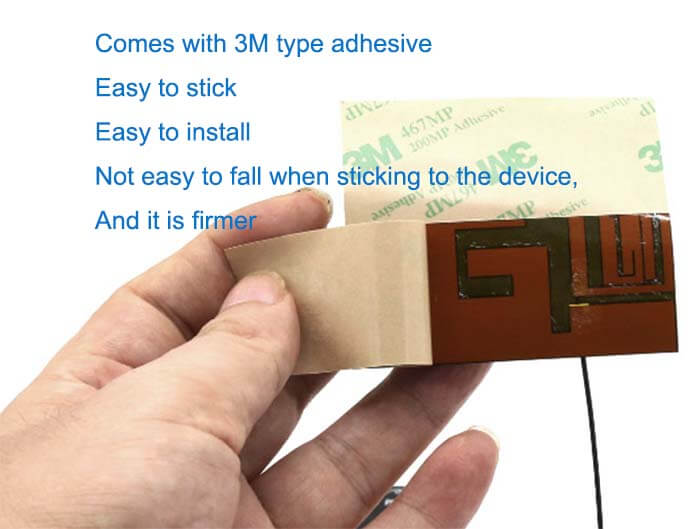
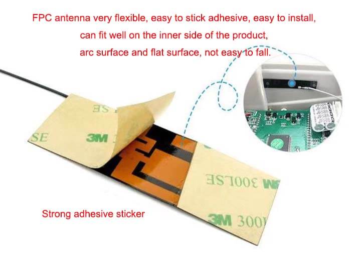
| Mounting | Connector/Sticker |
| Safety Emission and other | RoHS Compliant |
| Applications | ISM/SCADA/Utilities, IoT/M2M, Wi-Fi/Bluetooth/Zigbee/Sigfox, etc. |
Mini Wifi Antenna Indoor FPC Antenna Flexible PCB Antenna Features
RG low-loss cable antenna extension antenna extender – C&T RF Antennas Inc
Mini Wifi Antenna Indoor FPC Antenna Applications

How to design a PCB antenna?
The function of the antenna is to radiate radio frequency signals into free space. At this time, choosing a suitable antenna has a great influence on the transmission distance. Antennas are very sensitive to the surrounding environment.
In many cases, even if a suitable antenna is selected, the expected effect will not be achieved. Because some customers are not clear about the factors that need to be considered in antenna design, here we give some experience in actual engineering design so that customers can better design their own circuits and PCBs and increase the chances of project success.
1. Matching circuit design
When designing the schematic diagram, it is necessary to reserve a π-type network between the antenna and the RF output pin of the module.
The impedance of the antenna is affected by factors such as the PCB floor, the installation of the antenna, and the surrounding metal. This network is reserved to match the antenna to 50 ohms when it deviates significantly from the 50-ohm impedance.
X1, X2, and X3 are all reactance components. If the antenna is a standard 50-ohm impedance, then X2 and X3 do not need to be soldered, and X1 is connected to a 220PF capacitor or a 0-ohm resistor.
In PCB design, these three devices have been as close as possible to the RF output pin of the module, and the connected transmission line is short and straight. Do not lay ground in the 1.5mm area around the matching component to reduce the influence of parasitic parameters on the matching circuit.
2. Microstrip line design
In PCB design, since the output impedance of most antennas and modules is 50 ohms, in order to minimize energy reflection during transmission, the PCB lead between the RF output pin and the antenna should be a 50-ohm microstrip line. The commonly used board is FR4 (dielectric constant 4.2-4.6).
According to experience, when the line width is about 2.2 times the distance between the microstrip line and the reference layer, the characteristic impedance of the microstrip line is about 50 ohms.
In the specific design, it is recommended to use microstrip line impedance control tools (ADS, tx line, etc.) to calculate and complete the design of the microstrip line through actual debugging.
3. The influence of metal on the antenna
If there are metal objects near the antenna, the metal can reflect electromagnetic waves, which will not only affect the actual usable space of the antenna, but also increase the loss resistance of the antenna, reduce the radiation efficiency, and cause the deterioration of the antenna’s radiation performance.
When installing the antenna, pay attention to:
A: The antenna must be at least 5mm away from the battery;
B: The antenna must be at least 4mm away from the shielding case;
C: Do not use spray paint or plating with metallic components on the surface of the housing where the housing needs to be installed.
Reviews
There are no reviews yet.