Description
What is LTE PCB Antenna Indoor 4G Antenna?
The CTRF-ANTENNA-PCB-7027-3506-IPEX LTE PCB Antenna Indoor 4G Antenna is manufactured by C&T RF Antennas Inc. which operates on frequencies from 698 MHz to 2.7 GHz and is used for LTE, DAS, IoT, M2M, and telemetry applications.
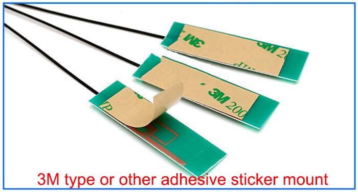
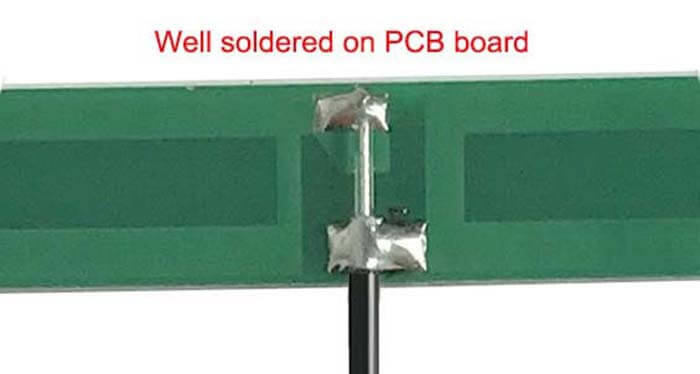
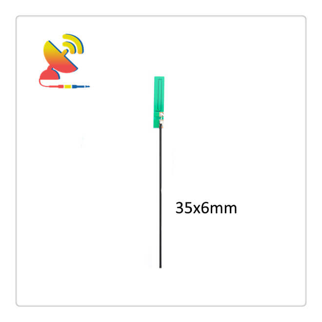
The LTE PCB Antenna Indoor 4G Antenna comes with a small PCB trace antenna size 35x6mm, 1 to 3dBi gain, 100mm RG 1.13 cable extender, built-in antenna for 4G terminals.
C&T RF Antennas Inc. is the Embedded 4G LTE PCB Antenna manufacturer in China. we provide the 4G LTE antenna with the internal antenna types and external antenna types.
C&T RF Antennas Inc provides internal & external antennas with antenna radio frequencies such as NFC, 169MHz, 230MHz, 315MHz, 433MHz, 868MHz, 915MHz, VHF&UHF, Lora, NB-IoT, ADS-B, GSM, GNSS, GPRS, 1.2 GHz, 1.4 GHz, 1.8 GHz, Wi-Fi 2.4 GHz, 5.8 GHz, Cellular 2G, 3G, 3.5 GHz, 4G LTE, GPS, 5G NR, 6G, etc.
C&T RF Antennas Inc. provides RF antennae with Omni & Directional antenna types such as Dipole Antennas, Whip Antennas, Marine Antennas, Router Antennas, MIMO Antennas, Combo Antennas, PCB Antennas, FPC Antennas, Spring Antennas, Magnetic Antennas, Sector Antennas, Yagi Antennas, and Accessories, etc, for IoT & M2M industries.
Contact us for the LTE PCB Antenna Indoor 4G Antenna for more details such as LTE PCB Antenna datasheet, LTE PCB Antenna pricing, LTE PCB Antenna inventory, or other 4G LTE PCB Antenna types.
Indoor 4G LTE PCB Antenna Specifications:
Indoor 4G LTE PCB Antenna Electrical Specifications |
|
| RF Antenna Type | PCB Antenna |
| Model | CTRF-ANTENNA-PCB-7027-3506-IPEX |
| Frequency | 698-960MHz, 1710-2700MHz |
| Gain | 1dBi/3dBi |
| VSWR | ≤2.5 |
| Impedance | 50 Ω |
| Polarization | Vertical/Linear |
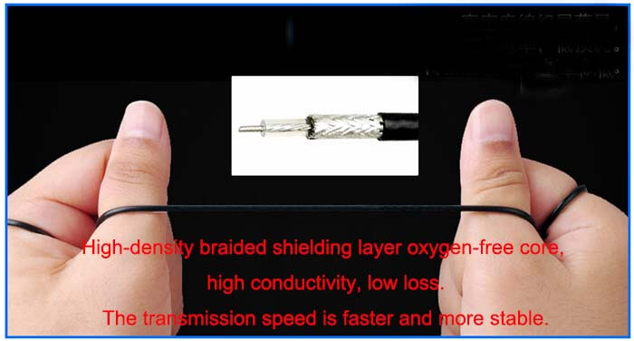
| Cable Type | RG1.13 |
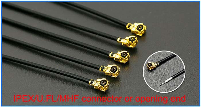
| Connector | U.FL/IPEX |
| Cable Length | 100mm |
| Lightning Protection | DC-Ground |
Indoor 4G LTE PCB Antenna Mechanical Specifications |
|
| PCB Board Dimension | 35*6mm |
| Weight | Approx. 3g |
| Material | PCB + RG Cable + U.FL connector |
| Operation Temperature | -40˚C ~ +65˚C |
| Storage Temperature | -40˚C ~ +70˚C |
| Color | Green |
| Antenna Design | Dipole Antenna |
| Mounting | Connector/Peel-and-stick |
| Safety Emission and other | RoHS Compliant |
| Applications | ISM/SCADA/Utilities, IoT/M2M/NB-IoT/LoRa, 2G 3G 4G LTE/LTE-IoT, GSM GPRS UMTS, etc. |
4G LTE PCB Antenna Features
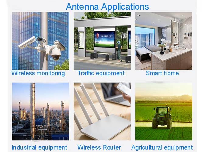
4G LTE PCB Antenna Applications
What is a 4G Antenna?
1. 4G Antenna Antenna is a device that converts high-frequency current or energy of the waveguide method into electromagnetic waves and emits them in a regular direction or restores electromagnetic waves from a certain direction to high-frequency currents.
Second. 4G antenna classification
1) Classified by purpose
Can be divided into communication antennas, TV antennas, radar antennas, etc.;
2) Classified by operating frequency band
Can be divided into short wave antenna, ultra-short wave antenna, microwave antenna, etc.;
3) Classified by direction
Can be divided into the omnidirectional antenna, directional antenna, etc.;
4) Classified by shape
It can be divided into linear antennas, planar antennas, etc.
Third. An omnidirectional antenna.
The omnidirectional antenna is, it shows uniform radiation at 360° on the horizontal pattern, which is also called non-directional, and on the vertical pattern, it appears as a beam with a certain width. In general, the lobe width The smaller the value, the greater the gain.
Fourth. Directional antenna
The directional antenna shows a certain angle of planned radiation on the horizontal pattern, that is, it is usually said to be directional, and it shows a beam with a certain width on the vertical pattern. Like the omnidirectional antenna, the lobe The smaller the width, the greater the gain.
Fifth. 4G Antenna Gain
Gain refers to the ratio of the power density of the signal generated by the actual antenna and the aspiring radiating unit at the same point in space under the condition of the input power being flat.
It quantitatively describes the degree to which an antenna gathers and radiates the input power. The gain is obviously closely related to the antenna pattern. The narrower the main lobe of the pattern and the smaller the side lobe, the higher the gain.
The physical meaning of gain can be understood in this way in order to generate a signal of a certain size at a certain point at a certain interval.
If an aspirational non-directional point source is used as the transmitting antenna, 100W input power is required, When using a directional antenna with a gain of G = 13 dB = 20 as the transmitting antenna, the input power only needs to be 100/20 = 5W.
In other words, the gain of a certain antenna, in terms of its radiation effect in the direction of maximum radiation, is the multiple of the input power amplification compared with a non-directional aspiration point source.
Sixth. 4G antenna operating frequency planning
Bandwidth Whether it is a transmitting antenna or a receiving antenna, they always work within a certain frequency plan/bandwidth. There are two different definitions for the bandwidth of an antenna.
One is the operating frequency bandwidth of the antenna under the condition of standing wave ratio SWR ≤ 1.5;
The other means that the antenna gain decreases by 3 decibels in the planned bandwidth.
In the mobile communication system, it is usually defined according to the former one. Specifically, the bandwidth of the antenna is the operating frequency planning of the antenna when the standing wave ratio SWR of the antenna does not exceed 1.5.
Generally speaking, at each frequency point within the operating bandwidth, the antenna function is different, but the function degradation caused by this difference is tolerable.

Reviews
There are no reviews yet.