Description
What is IPEX IPX UFL Cable To SMA Female Bulkhead Cable Assembly?
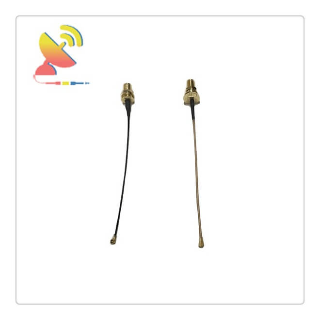
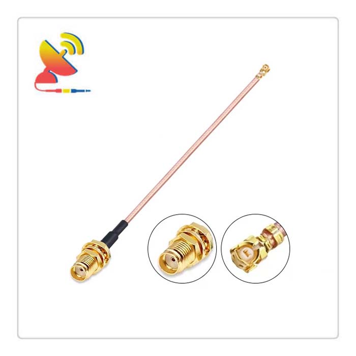
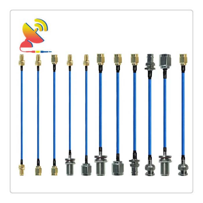
The IPEX To SMA Female Cable Assembly CTRF-ANTENNA-CC-SMAK-IPEX-RG113-100 coaxial cable assembly comes with SMA female to IPEX, IPX, U.FL male connector black cable RG1.13 low loss coax cable pigtail antenna extender.
Plug Type: U.FL Mini PCI to SMA Female (NO pin in the center)
Coaxial low loss RG-1.13 cable, each cable length: 4″ (10cm). To maximize signal power, ensure the highest quality of all types of connected frequency equipment, and eliminate the attenuation of signal power in a cable of this length, we have especially used high-quality copper RG cable
Impedance: 50 Ohm, Metall: copper
Simple connection and disconnection Applications include Mobile phones, WLAN, Mini PCI, Bluetooth, PDA, GPS, electronic measuring instruments, etc.
C&T RF Antennas Inc provides internal & external antennas with antenna radio frequencies such as NFC, 169MHz, 230MHz, 315MHz, 433MHz, 868MHz, 915MHz, VHF&UHF, Lora, NB-IoT, ADS-B, GSM, GNSS, GPRS, 1.2 GHz, 1.4 GHz, 1.8 GHz, Wi-Fi 2.4 GHz, 5.8 GHz, Cellular 2G, 3G, 3.5 GHz, 4G LTE, GPS, 5G NR, 6G, etc.
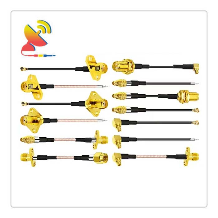
C&T RF Antennas Inc. provides RF antennae with Omni & Directional antenna types such as Dipole Antennas, Whip Antennas, Marine Antennas, Router Antennas, MIMO Antennas, Combo Antennas, PCB Antennas, FPC Antennas, Spring Antennas, Magnetic Antennas, Sector Antennas, Yagi Antennas, and Accessories, etc, for IoT & M2M industries.
The IPEX IPX UFL Cable To SMA Female Bulkhead Cable Assembly is available at C&T RF Antennas Inc.
Contact us for more IPEX IPX UFL Cable To SMA Female Bulkhead Cable Assembly details such as IPEX IPX UFL Cable To SMA Female Bulkhead Cable Assembly datasheet, IPEX IPX UFL Cable To SMA Female Bulkhead Cable Assembly price, and IPEX IPX UFL Cable To SMA Female Bulkhead Cable Assembly inventory.
Or other Cable Assemblies.
Key Specifications of the IPEX To SMA Female Cable Assembly
| Item NO.: CTRF-CC-SMAK-IPEX-RG113-100 | |
| Connector Series 1 | SMA |
| Connector Gender 1 | Female |
| Connector Polarity 1 | Standard |
| Connector Angle 1 | Straight |
| Connector Mount Method 1 | None |
| Connector Impedance 1 | 50 |
| Connector Series 2 | U.FL |
| Connector Gender 2 | Female |
| Connector Polarity 2 | Standard |
| Connector Angle 2 | Straight |
| Connector Mount Method 2 | None |
| Connector Impedance 2 | 50 |
| RF Cable Part Number | RG1.13 |
| RF Cable Type | RG1.13 |
| RG Cable Length | 100mm |
| Color | Black |
| Frequency | DC 0-6Ghz |
| V.S.W.R | 1.5 |
| Voltage Breakdown | DC1000V/50Hz |
| Insertion Loss | ≤0.1dB/GHz |
| Insulation Resistance | ≥5000MΩ |
| Contact Resistance | Shell≤2.5mΩ; Center Pin≤3mΩ |
| Center Pin Retention | ≥50g |
| Mating Cycles | >500 |
| Operation Temperature | -40℃~+65℃ |
| Storage Temperature | -40℃~+80℃ |
| Junction Retention | ≥8KG |
RF Coaxial Cable
Main categories of coaxial cables
Coaxial cables can be divided into two basic types, baseband coaxial cables, and broadband coaxial cables.
1. Baseband coaxial cable
The shielding layer of the baseband coaxial cable is usually a copper mesh structure, and its characteristic impedance is 50Ω.
This cable is used to transmit digital signals, and the commonly used models are generally RG-8 (thick cable) and RG-58 (thin cable). The most intuitive difference between thick and thin cables is the cable diameter.
Thick cable is suitable for relatively large local networks. It has a long standard distance and high reliability; however, the thick cable network must be equipped with transceivers and transceiver cables, which are difficult to install, so the overall cost is high.
On the contrary, thin cable is relatively simple and cheaper; but because the cable has to be cut during the installation process, it is easy to cause the hidden danger of poor contact when there are many connectors.
Whether it is a network connected by a thick cable or a thin cable, the point of failure often affects all the machines on the entire cable, and the diagnosis and repair of the fault are very troublesome. Therefore, baseband coaxial cables have been gradually replaced by unshielded twisted pairs or optical cables.
2. Broadband coaxial cable
The shielding layer of broadband coaxial cable is usually stamped with aluminum, and its characteristic impedance is 75Ω. This kind of cable is usually used to transmit analog signals. The commonly used model is RG-59.
It is a standard transmission cable used in cable television networks. It can transmit multiple channels of TV signals simultaneously in one cable. Broadband coaxial cable can also be used as the transmission medium of some computer networks.
Working principle
The coaxial cable is divided into four layers from inside to outside: the central copper wire (single-strand solid wire or multi-stranded wire), plastic insulator, mesh conductive layer, and wire sheath. The central copper wire and the mesh conductive layer form a current loop.
It is named because of the coaxial relationship between the central copper wire and the meshed conductive layer.
Coaxial cables conduct alternating current instead of direct current, which means that the direction of the current is reversed several times per second.
If a general wire is used to transmit high-frequency current, this wire will be equivalent to an antenna that emits radio outwards. This effect loses the power of the signal and reduces the strength of the received signal.
The coaxial cable is designed to solve this problem. The radio emitted by the central wire is isolated by the mesh conductive layer, which can be grounded to control the emitted radio.
There is also a problem with coaxial cables. If a certain section of the cable is squeezed or distorted, the distance between the center wire and the mesh conductive layer is not consistent, which will cause the internal radio waves to be affected. Reflect back to the source of the signal.
This effect reduces the receivable signal power.
To overcome this problem, a layer of the plastic insulator is added between the center wire and the meshed conductive layer to ensure that the distance between them is consistent. This also causes the cable to be relatively rigid and not easy to bend.
The shielding material of the coaxial cable is essentially the improvement of the outer conductor, from the initial tubular outer conductor to a single-layer braid and double-layer metal. Although the tubular outer conductor has very good shielding performance, it is not easy to bend and inconvenient to use.
The shielding efficiency of single-layer braiding is the worst, and the transfer impedance of double-layer braiding is 3 times lower than that of one-layer braiding.
It can be seen that the shielding effect of double-layer braiding has been greatly improved compared with single-layer braiding. Major coaxial cable manufacturers are constantly improving the outer conductor structure of the cable to maintain its performance.
Advantages and disadvantages of coaxial cable
The advantage of coaxial cable is that it can support high-bandwidth communication on relatively long lines without repeaters, but its disadvantages are also obvious:
One is a large size, the diameter of the thin cable is 3/8 inch thick, which takes up a lot of space in the cable duct;
The second is the inability to withstand tangles, pressures, and severe bends, which will damage the cable structure and prevent signal transmission; the last is the high cost, and all these shortcomings can be overcome by twisted pair.
Therefore, in the current LAN environment, It has been replaced by the Ethernet physical layer specification based on twisted pair.
installation method
Coaxial cables are generally installed between equipment and equipment. Each user position is equipped with a connector to provide an interface for the user.
The installation method of the interface is as follows:
(1) Thin cable: Cut the thin cable, install BNC headers on both ends, and then connect to both ends of the T-connector.
(2) Thick cable: The thick cable is generally installed with a tap device similar to a splint, which uses the guide pin on the Tap to penetrate the insulation layer of the cable and directly connect to the conductor. Terminals are provided at both ends of the cable to weaken the reflection of the signal. Used in a network with a transmission rate of 10Mbit/s.
Parameter index
Electrical parameters
(1) The characteristic impedance of the coaxial cable: The average characteristic impedance of the coaxial cable is 50±2Ω, the periodic change of the impedance along a single coaxial cable is a sine wave, the center average value is ±3Ω, and its length is less than 2 meters.
(2) Coaxial cable attenuation: generally refers to the attenuation value of a 500-meter-long cable section. When measuring with a 10MHz sine wave, its value does not exceed 8.5db (17db/km); when measuring with a 5MHz sine wave, its value does not exceed 6.0db (12db/km).
(3) The propagation speed of the coaxial cable: The minimum propagation speed required is 0.77C (C is the speed of light).
(4) Coaxial cable DC loop resistance: the sum of the resistance of the center conductor of the cable and the resistance of the shielding layer does not exceed 10 milliohms/meter (measured at 20°C).
Physical parameter
A coaxial cable is composed of a central conductor, an insulating material layer, a shielding layer composed of mesh fabric, and an outer isolation material layer.
The coaxial cable is flexible enough to support a bending radius of 254mm (10 inches). The central conductor is a solid copper wire with a diameter of 2.17mm±0.013mm. The insulating material must meet the electrical parameters of the coaxial cable.
The shielding layer is composed of metal strips or sheets that meet the transmission impedance and ECM specifications. The inner diameter of the shielding layer is 6.15mm and the outer diameter is 8.28mm. The external insulation material generally uses polyvinyl chloride (such as PVC) or similar materials.
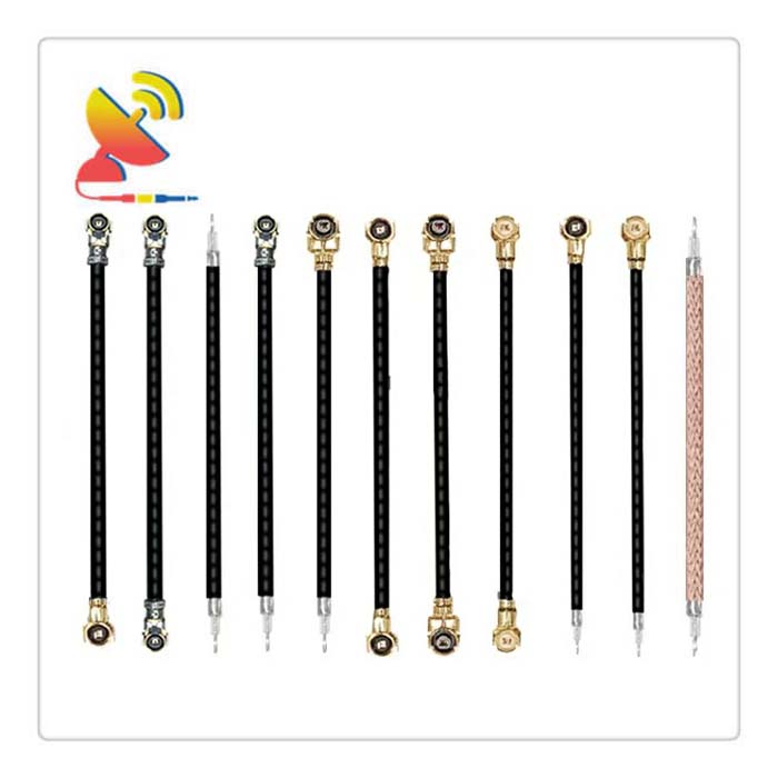
Similar RG Cable Assemblies
Reviews
There are no reviews yet.