Description
What is a High Gain 4G Antenna Indoor PCB Antenna?
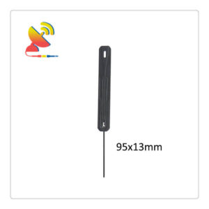
The High gain 4G Antenna Indoor PCB Antenna Item Model CTRF-ANTENNA-PCB-7027-9513-IPEX is an indoor 4G antenna PCB-based board LTE antenna with a 6/8dBi high-gain & high-performance 4G Antenna Indoor PCB Antenna manufactured by C&T RF Antennas Inc.
C&T RF Antennas Inc. is targeting the fast-increasing 3G 4G mobile device market with PCB antennas for 3G and 4G applications operating at GSM850, GSM900, DCS1800, PCS1900, and WCDMA2100, Wifi 2400-2500, 4G 2700 and will provide full coverage of the 3G 4G bands in all world regions.
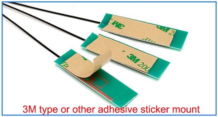
The PCB antennas are designed to be mounted inside a small mobile or wearable device and are supplied with a cable and a connector so that they are very easy to integrate into a design.
They have a readily applied adhesive with a peel-off strip making them easy to fit inside the casing of a product.
4G Antenna Indoor PCB Antenna comes with a 698-960MHz, 1710-2700MHz 4g frequency, 4dBi/6dBi high-gain, RG1.13 cable extender, Ipex connector.
We provide the 4G antenna with many antenna types such as PCB antenna, flexible PCB antenna, rubber duck antenna, fiberglass antenna, through-hole mount antenna, etc.
C&T RF Antennas Inc provides internal & external antennas with antenna radio frequencies such as NFC, 169MHz, 230MHz, 315MHz, 433MHz, 868MHz, 915MHz, VHF&UHF, Lora, NB-IoT, ADS-B, GSM, GNSS, GPRS, 1.2 GHz, 1.4 GHz, 1.8 GHz, Wi-Fi 2.4 GHz, 5.8 GHz, Cellular 2G, 3G, 3.5 GHz, 4G LTE, GPS, 5G NR, 6G, etc.
C&T RF Antennas Inc. provides RF antennae with Omni & Directional antenna types such as Dipole Antennas, Whip Antennas, Marine Antennas, Router Antennas, MIMO Antennas, Combo Antennas, PCB Antennas, FPC Antennas, Spring Antennas, Magnetic Antennas, Sector Antennas, Yagi Antennas, and Accessories, etc, for IoT & M2M industries.
C&T RF Antennas Inc Offers all kinds of internal antennas & external antennas and 5G/LTE/NB-IoT/WCDMA/GNSS/Wi-Fi/GSM antennas.
Contact us for more details such as 4G Antenna Indoor PCB Antenna datasheet, 4G Antenna Indoor PCB Antenna pricing, and 4G Antenna Indoor PCB Antenna inventory, or other 4G Antenna Indoor PCB Antenna types.
4G Antenna Indoor PCB Antenna Specifications:
4G Antenna Indoor PCB Antenna Electrical Specifications |
|
| RF Antenna Type | Built-in PCB Antenna |
| Model | CTRF-ANTENNA-PCB-7027-9513-IPEX |
| Frequency | 698-960MHz, 1710-2700MHz |
| Gain | 6dBi/8dBi |
| VSWR | ≤2.5 |
| Impedance | 50 Ω |
| Polarization | Vertical/Linear |
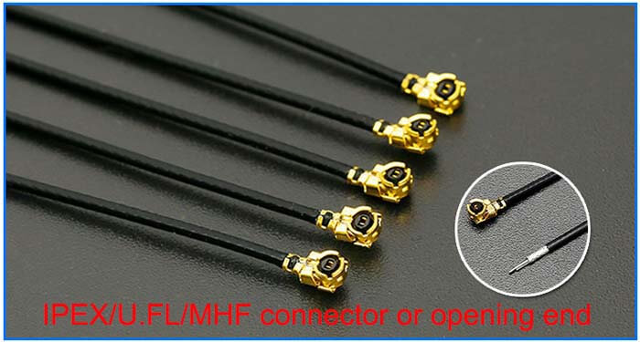
| Cable Type | RG1.13 |
| Connector | U.FL/IPEX |
| Cable Length | 100mm |
| Lightning Protection | DC-Ground |
4G Antenna Indoor PCB Antenna Mechanical Specifications |
|
| PCB Board Dimension | 95*13mm |
| Weight | Approx. 5g |
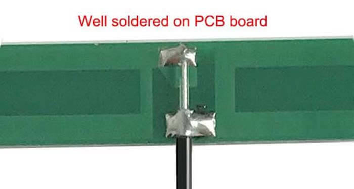
| Material | PCB + RG Cable + U.FL connector |
| Operation Temperature | -40˚C ~ +65˚C |
| Storage Temperature | -40˚C ~ +70˚C |
| Color | Black |
| Antenna Design | Dipole Antenna |
| Mounting | Connector/Peel-and-stick |
| Safety Emission and other | RoHS Compliant |
| Applications | ISM/SCADA/Utilities, IoT/M2M/NB-IoT/LoRa, 2G 3G 4G LTE/LTE-IoT, GSM GPRS UMTS, etc. |
4G Antenna Indoor PCB Antenna Features
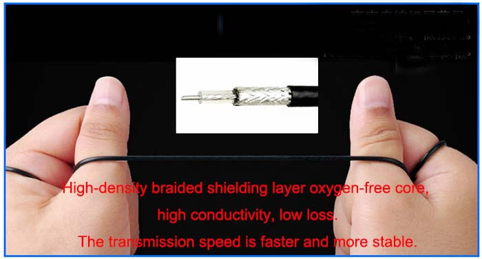
RG low-loss cable antenna extension antenna extender – C&T RF Antennas Inc
4G Antenna Indoor PCB Antenna Applications

Mobile phone built-in antenna classification
1. PIFA Picofarad Antenna
A. The radiator area of the antenna structure is 550~600mm2, and the distance (height) from the TOP surface of the PCB mainboard is 6~7mm.
The antenna and the mainboard have two feed points, one is the antenna module output, and the other is the RF ground. The location of the antenna is at the top of the phone.
If the PIFA pico-fat antenna is designed according to the requirements of the environmental structure, the electrical performance is quite superior, including the SAR index, it is the first choice for the built-in antenna.
It is suitable for mobile phone products with a certain thickness, folding, sliding cover, screwing cover, and bar machines.
B. There is a complete floor in the projection area of the mainboard antenna, and no components should be arranged on the antenna side, especially components with large metal structures such as motors, SPEAKER, RECEIVER, FPC cables, LDOs, and low-frequency drive components.
They have a great negative impact on the electrical performance of the antenna.
C. The feed position and spacing of the antenna are generally recommended to be designed at the top left or top right; the spacing is between 4 and 5 mm.
2. Several structural methods of PIFA antenna
A. Bracket
The antenna consists of a plastic bracket and a metal sheet (radiator). The metal sheet and the plastic bracket are fixed by hot melt.
ABS or PC materials are commonly used for plastics, and beryllium copper, phosphor copper, and stainless steel sheets are commonly used for metals. FPC can also be used, but two PINs need to be added to the mainboard, and the cost of these two items is slightly higher.
B. Attached
Attach the metal sheet (radiator) directly to the back shell of the phone. The fixing method generally uses a hot melt structure. Adhesive methods are also used, but because the structure is not very stable, it is rarely used. The same is true for FPC.
3. MONOPOLE (MLK) monopole antenna
A. Antenna structure
The area of the radiator is 300~350mm2, and the distance (height) from the TOP surface of the PCB is 3~4mm. The relative distance between the antenna radiator and the PCB should be greater than 2mm. The antenna and the mainboard have only one feed point, which is the output of the module.
The location of the antenna is on the top or bottom of the phone.
If the MONOPOLE monopole antenna is designed according to the requirements, the electrical performance can reach a higher level. The disadvantage is that the SAR is slightly higher. It is not suitable for folding and sliding cover machines and has advantages in bar machines and ultra-thin bar machines.
B. Motherboard
The antenna projection area must not have a floor or PCB and should not arrange components with large metal structures such as motors, speakers, receivers, etc. Since the electrical performance of monopole antennas is particularly sensitive to metals, it can not even be achieved.
C. The location of the feed point of the antenna
It is different from the PIFA method. It is generally recommended to design on the four corners of the antenna.
4. Several structural methods of MONOPOLE monopole antenna
A. Same as PIFA antenna, with bracket type and attached type.
B. The radiator of the PCB-type MONOPOLE monopole antenna adopts the PCB board, and the feed with the mainboard has reed and PIN methods and is thermally fused on the plastic bracket. It can also be installed with a positioning hook on the casing.
C. The special structure antenna is designed on the top elevation (thickness) of the mobile phone and is formed by metal wire.
Reviews
There are no reviews yet.