Description
What is an Extra-wide Band Antenna Internal PCB Antenna?
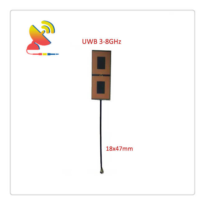
The Extra-wide Band Antenna Internal PCB Antenna CTRF-ANTENNA-PCB-300800-4718-IPEX is an indoor PCB board antenna with 100mm coax RG1.13 cable 47x18mm size PCB design UWB antenna from 3000-8000Mhz UWB antenna manufactured by C&T RF Antennas Inc for wireless applications.
The 3GHz-8GHz Extra-wide Band Antenna PCB antenna is manufactured by C&T RF Antennas Inc, the Extra-wide Band Antenna manufacturer also with the other antenna types in China.
C&T RF Antennas Inc provides internal & external antennas with antenna radio frequencies such as NFC, 169MHz, 230MHz, 315MHz, 433MHz, 868MHz, 915MHz, VHF&UHF, Lora, NB-IoT, ADS-B, GSM, GNSS, GPRS, 1.2 GHz, 1.4 GHz, 1.8 GHz, Wi-Fi 2.4 GHz, 5.8 GHz, Cellular 2G, 3G, 3.5 GHz, 4G LTE, GPS, 5G NR, 6G, etc.
C&T RF Antennas Inc. provides RF antennae with Omni & Directional antenna types such as Dipole Antennas, Whip Antennas, Marine Antennas, Router Antennas, MIMO Antennas, Combo Antennas, PCB Antennas, FPC Antennas, Spring Antennas, Magnetic Antennas, Sector Antennas, Yagi Antennas, and Accessories, etc, for IoT & M2M industries.
Contact us for more 3GHz-8GHz Extra-wide Band Antenna details such as Extra-wide Band Antenna datasheet, Extra-wide Band Antenna pricing, Extra-wide Band Antenna inventory, etc.
3GHz-8GHz Extra-wide Band Antenna Specifications
3GHz-8GHz Extra-wide Band Antenna Electrical Specifications |
|
| RF Antenna Type | PCB Antenna |
| Model | CTRF-ANTENNA-PCB-300800-4718-IPEX |
| Frequency | 3000-8000MHz |
| Gain | 3dBi/5dBi |
| VSWR | ≤3.0 |
| Impedance | 50 Ω |
| Polarization | Vertical/Linear |
| Connector | Ipex/U.FL |
| Lightning Protection | DC-Ground |
3GHz-8GHz Extra-wide Band Antenna Mechanical Specifications |
|
| PCB Board Dimension | 47*18mm |
| Weight | Approx. 4g |
| Material | PCB Board |
| Operation Temperature | -40˚C ~ +75˚C |
| Storage Temperature | -40˚C ~ +80˚C |
| Color | Brown |
| Antenna Design | Dipole Antenna |
| Mounting | Screw/Peel-and-Stick |
| Safety Emission and other | RoHS Compliant |
3GHz-8GHz PCB Antenna Features
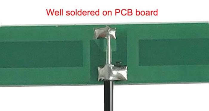
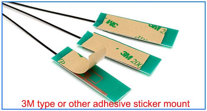
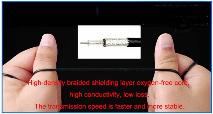
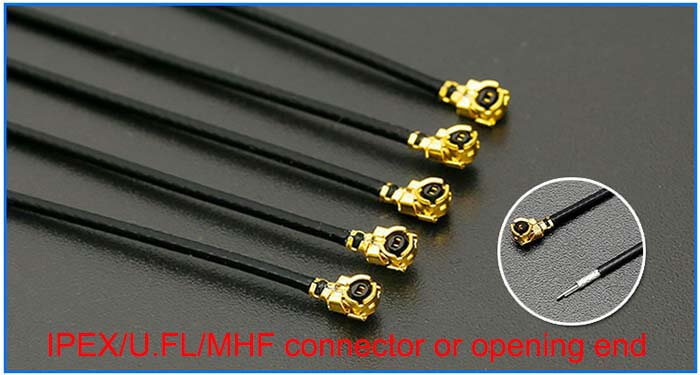
UWB technology
The original definition of UWB came from the impulse communication technology that emerged in the 1960s, also known as impulse radio (Impulse Radio) technology.
Different from the carrier modulation technology widely used in today’s communication systems, this technology uses baseband pulses with steep rising and falling edges to communicate directly, so it is also called baseband transmission or carrier technology.
The pulse length of pulsed UWB technology is usually on the order of sub-nanoseconds, and the signal bandwidth often reaches several gigahertz, which is much larger than the bandwidth of any existing wireless communication technology.
Broadband technology.
Early ultra-wideband technology (UWB) was used for short-distance transmission of big data and has been applied in wireless positioning applications in recent years.
Positioning accuracy: centimeter-level, 10-centimeter level, sub-meter level.
Positioning range: tens of meters are arranged between base stations, and positioning can be performed within this range, generally 3 or 4 points are required.
Positioning algorithm: TDOA/TOF(time of flight method), pure TDOA has low accuracy and uneven distribution, comprehensive application to ensure accuracy.
System architecture: Tof does not require synchronization; TDOA’s previous generation technology requires complex synchronization equipment, and the new generation technology does not require a synchronization machine to improve system reliability.
Performance advantages: high accuracy (the only indoor wireless positioning solution that can meet the sub-meter level), high capacity, and low power consumption. It is the mainstream of precise positioning in the future.
Performance disadvantages: Human body occlusion will reduce accuracy to a certain extent, and mature and stable algorithms and system-level solutions are required to ensure accuracy.
UWB pulse technology
Hermite quadrature pulse
Hermite pulse is a kind of orthogonal pulse shaping method first proposed for a high-speed UWB communication system. Combining multi-ary pulse modulation can effectively increase the system transmission rate.
This type of pulse waveform is derived from Hermite polynomials. The characteristic of this pulse shaping method is that the energy is concentrated in the low frequency, the frequency spectrum of each order of the waveform is very different, and the carrier must be used to move the spectrum to meet the FCC requirements.
PSWF orthogonal pulse
PSWF pulse is a kind of approximate “time limit-band limit” signal, which has a very ideal effect in the analysis of the band limit signal.
Compared with Hermite pulses, PSWF pulses can be designed directly according to the target frequency band and bandwidth requirements, without the need for complex carrier modulation to shift the spectrum.
Therefore, the PSWF pulse is a non-carrier shaping technology, which is beneficial to simplify the complexity of the transceiver.

Reviews
There are no reviews yet.