Description
What is a 2.4GHz-10.5GHz Embedded PCB Antenna For UWB Applications?
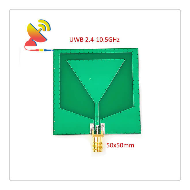
The 2.4GHz-10.5GHz UWB antenna CTRF-ANTENNA-PCB-2401050-5050-SMA Embedded PCB Antenna For UWB Applications is an extra-wide band antenna with a 2.4GHz to 10.5GHz UWB antenna female PCB connector SMA antenna manufactured by C&T RF Antennas Inc.
The 2.4GHz-10.5GHz Embedded PCB Antenna For UWB Applications Is Available At C&T RF Antennas Inc. The leading ultra wide-band antenna UWB PCB antenna manufacturer in China.
C&T RF Antennas Inc provides internal & external antennas with antenna radio frequencies such as NFC, 169MHz, 230MHz, 315MHz, 433MHz, 868MHz, 915MHz, VHF&UHF, Lora, NB-IoT, ADS-B, GSM, GNSS, GPRS, 1.2 GHz, 1.4 GHz, 1.8 GHz, Wi-Fi 2.4 GHz, 5.8 GHz, Cellular 2G, 3G, 3.5 GHz, 4G LTE, GPS, 5G NR, 6G, etc.
C&T RF Antennas Inc. provides RF antennas with Omni & Directional antenna types such as Dipole Antennas, Whip Antennas, Marine Antennas, Router Antennas, MIMO Antennas, Combo Antennas, PCB Antennas, FPC Antennas, Spring Antennas, Magnetic Antennas, Sector Antennas, Yagi Antennas, and Accessories, etc, for IoT & M2M industries.
Contact Us For More Info On 2.4GHz-10.5GHz Embedded PCB Antenna For UWB Applications such as Embedded PCB Antenna For UWB Applications datasheet, PCB Antenna For UWB Applications pricing, PCB Antenna For UWB Applications inventory, etc.
2.4GHz-10.5GHz PCB Antenna For UWB Applications Specifications
2.4GHz-10.5GHz PCB Antenna For UWB Applications Electrical Specifications |
|
| RF Antenna Type | PCB Antenna |
| Model | CTRF-ANTENNA-PCB-2401050-5050-SMA |
| Frequency | 2.4GHz-10.5GHz |
| Gain | 6dBi/8dBi |
| VSWR | ≤3.0 |
| Impedance | 50 Ω |
| Polarization | Vertical/Linear |
| Connector | SMA Female |
| Lightning Protection | DC-Ground |
2.4GHz-10.5GHz PCB Antenna For UWB Applications Mechanical Specifications |
|
| PCB Board Dimension | 50*50mm |
| Weight | Approx. 10g |
| Material | PCB Board |
| Operation Temperature | -40˚C ~ +75˚C |
| Storage Temperature | -40˚C ~ +80˚C |
| Color | Green |
| Antenna Design | Dipole Antenna |
| Mounting | Screw |
| Safety Emission and other | RoHS Compliant |
Ultra-wideband (UWB) Technology
The emergence of ultra-wideband (UWB) is related to the following terms, namely pulse, no carrier, baseband, time domain, non-sinusoidal, orthogonal function, and large relative bandwidth wireless/radar signal. Here, UWB is used for unified expression.
In the 1960s, design techniques for UWB transmitters and receivers appeared, and UWB has also been applied in communications and radar.
Since then, UWB technology has been continuously developed. By the 1970s, all system concepts related to UWB in communications and radar applications had been established, but the real introduction of the name UWB was still in the 1980s.
Later, in the 1990s, due to the advancement of equipment manufacturing technology, the first UWB commercial system appeared.
The current work is the specific realization of this system, so that the basic structure, specific details, and implementation methods of UWB are all Some progress has been made, which has further promoted the practical process of UWB.
UWB wireless systems used in military radars and disaster rescue searches have already been used abroad. Now, due to the unique performance of UWB wireless communication and the continuous improvement of the level of microelectronics technology and devices in recent years, UWB is at a low cost.
The application of short- and medium-distance wireless communication is becoming more and more attractive, especially in meeting the increasing demand for wired Internet access is a major driving force for the research of short-distance wireless technology.
UWB technology is a low-power, high-bandwidth, and relatively simple wireless communication technology.
It has the advantages of low system complexity, low transmit signal power spectrum density, insensitivity to channel fading, low interception capability (LPI/D), and high positioning accuracy.
It is especially suitable for high-speed wireless access in dense multipath places such as indoors.
The key technology of the UWB system
UWB’s name comes from the ability to transmit signals over a very wide bandwidth, that is, ultra-wideband bandwidth. The so-called ultra-wideband bandwidth, according to the definition of the Federal Communications Commission (FCC), is: 25% higher than the center frequency or a bandwidth greater than 1.5 GHz.
For example, a signal with a center frequency of 4 GHz will span the range from 3.5 GHz (or lower) to 4.5 GHz (or higher) in order to be called a UWB signal.
The key technologies of UWB wireless systems mainly include the method of generating pulse signal trains (transmitting sources), the modulation method of pulse trains, the effective antenna design method, and the receiver design method suitable for UWB.
UWB pulse signal generation
In essence, generating a signal source with an extremely short pulse width (ns level) is the basic prerequisite for studying UWB technology. For example, a single carrier-free narrow pulse signal has two outstanding characteristics:
One is that the waveform of the excitation signal is steep A single short pulse at the leading edge; the second is that the excitation signal includes a wide spectrum, from direct current (DC) to microwave bands.
There are two types of methods for generating pulse sources:
(1) In The photoelectric method, the basic principle is to use the steep rising edge at the moment when the photoconductive switch is turned on to obtain the pulse signal. Since the laser pulse signal used as the excitation source can have a very steep front, the pulse width obtained can reach the order of ps (10-12).
In addition, because the photoconductive switch is made by an integrated method, it can obtain good consistency, so it is the most promising method.
(2) The basic principle of the electronic method is to reversely energize the semiconductor PN junction to make it reach the avalanche state, and at the moment of conduction, take the steep rising edge as the pulse signal.
This scheme is currently the most widely used. The disadvantage is that because the electric pulse signal is used as the trigger, its leading edge is wide, and the triggering accuracy is limited, especially when precise control of the pulse generation time is required, the control accuracy cannot be achieved.
In addition, due to the limitation of the withstand voltage characteristics of the transistor, this method generally can only generate pulses of tens of volts to hundreds of volts. Of course, the pulse width can be less than 1 ns.
The impulse pulse usually uses a Gaussian single-cycle pulse with a width of ns and a wide frequency spectrum. The actual communication uses a long series of pulses.
Due to the repetitive periodicity of the signal in the time domain, the spectrum will be discretized and interfere with traditional radio equipment and signals. Appropriate signal adjustments are needed to reduce this interference. Impact.
Modulation of information
Pulse position modulation (PPM) and pulse amplitude modulation (PAM) are the two main modulation methods of ultra-wideband radio. PPM is also called time modulation (TM), which uses the position of each pulse to be ahead of or behind a certain standard or specific time to express certain specific information.
Therefore, the modulation signal needs to be used at the receiving end to use matched filtering technology to Correct reception means that the modulation information is detected by the cross-correlator when it reaches zero phase difference, otherwise, the purpose of correct reception will not be achieved.
PAM is a modulation method that uses information symbols to control the pulse amplitude.
In the UWB system, when time-hopping pulse position modulation (TMPAM) is used to modulate a long pulse sequence, the next piece of information for each user will be randomly distributed in time, and a flatter RF signal power distribution can be obtained in the frequency domain.
This makes the UWB signal resemble background noise in the frequency domain.
The transmitter sends a single-period pulse on a time frame determined by a pseudo-random sequence, usually, 100 times the single-period pulse signal is the duration of the randomly occurring pulse, and its position is determined by the PN code.
The time-hopping spread spectrum controlled by the pseudo-random sequence is different from the general spread spectrum waveform (direct sequence spread spectrum or frequency hopping spread spectrum).
The spread spectrum bandwidth of the UWB waveform is directly generated, that is, a single bit is not spread by the PN code. Modulation is essentially the concept of the time domain.
Reviews
There are no reviews yet.