Description
What is the Best Long-Range Wifi Antenna Outdoor Yagi Antenna?
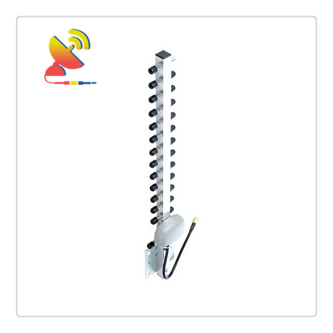
The CTRF-ANTENNA-YG-2450-50-SMA Wifi Yagi antenna is an outdoor directional Yagi antenna Long-range wifi antenna manufactured by C&T RF Antennas Inc. and is used for indoor-outdoor wireless signal transmission.
A Yagi antenna or a Yagi-Uda antenna is a directional antenna that radiates signals in one main direction. It consists of a long transmission line with a single driven element consisting of two rods connected on either side of the transmission line.
Long-Range Wifi Antenna Yagi Directional Antennas
The Long-Range Wifi Antenna Yagi antennas are typically frequency-specific (2400MHz to 2500MHz). You must match the antenna frequency with the frequency that your service provider is using in your area.
Although most carriers (and phones) can use multiple frequencies, a service provider usually uses only one of these frequencies in one particular area.
The Best Long-Range Wifi Antenna Outdoor Yagi Antenna CTRF-ANTENNA-YG-2450-50-SMA antenna item is supplied by C&T RF Antennas Inc., the indoor-outdoor Wi-Fi antenna manufacturer in China.
C&T RF Antennas Inc provides internal & external antennas with antenna radio frequencies such as NFC, 169MHz, 230MHz, 315MHz, 433MHz, 868MHz, 915MHz, VHF&UHF, Lora, NB-IoT, ADS-B, GSM, GNSS, GPRS, 1.2 GHz, 1.4 GHz, 1.8 GHz, Wi-Fi 2.4 GHz, 5.8 GHz, Cellular 2G, 3G, 3.5 GHz, 4G LTE, GPS, 5G NR, 6G, etc.
C&T RF Antennas Inc. provides RF antennae with Omni & Directional antenna types such as Dipole Antennas, Whip Antennas, Marine Antennas, Router Antennas, MIMO Antennas, Combo Antennas, PCB Antennas, FPC Antennas, Spring Antennas, Magnetic Antennas, Sector Antennas, Yagi Antennas, and Accessories, etc, for IoT & M2M industries.
Contact us for the Long-Range Wifi Antenna datasheet, Long-Range Wifi Antenna pricing, Long-Range Wifi Antenna inventory, or the Long-Range Wifi Antenna types.
Long-Range Wifi Antenna Outdoor Yagi Antenna Specifications:
Long-Range Wifi Antenna Outdoor Yagi Antenna Electrical Specifications |
|
| RF Antenna Type | Yagi Antenna |
| Model | CTRF-ANTENNA-YG-2450-50-SMA |
| Frequency | 2400-2500MHz |
| Gain | 20dBi |
| VSWR | ≤2.0 |
| Impedance | 50 Ω |
| Polarization | Vertical |
| Cable Type | RG58 |
| Connector | RP SMA |
| Cable Length | 1.5M |
| Max Power | 50W |
| Lightning Protection | DC-Ground |
Long-Range Wifi Antenna Outdoor Yagi Antenna Mechanical Specifications |
|
| Dimension | 49.5×6.8×1.6cm |
| Weight | Approx. 270g |
| Material | Aluminum |
| Operation Temperature | -40˚C~+85˚C |
| Storage Temperature | -40˚C~+80˚C |
| Units | 14 |
| Mounting | U Clamp/Adsorption |
| Safety Emission and other | RoHS Compliant |
| Standard | IEEE802.11b,IEEE802.11g,IEEE802.11n |
What is the working principle of the Yagi antenna?
The working principle of the Yagi antenna is as follows (take the three-element antenna reception as an example): the director is slightly shorter than the one-half wavelength, the main oscillator is equal to one-half wavelength, and the reflector is slightly longer than the one-half wavelength. The oscillator spacing is a quarter of a wavelength.
At this time, the director is capacitive to the induced signal, and the current leads the voltage by 90°; the electromagnetic wave induced by the director will radiate to the main oscillator, and the radiation signal will lag by 90° after a quarter-wavelength of the distance, which exactly offsets the previous
The lead caused by the two has the same phase, so the signal is superimposed and strengthened.
The reflector is slightly longer than one-half of the wavelength and is inductive. The current lags by 90°. In addition, when the radiation reaches the main oscillator, it lags by 90°.
The total difference between the two is just 180°, which has a canceling effect. Strengthen in one direction and weaken in the other direction, and then have strong directionality. The same is true for the launch state.
Antenna principle
An active vibrator is a key unit. There are two common forms: a folded vibrator and a straight vibrator. The straight oscillator is actually a half-wavelength dipole oscillator, and the reduced oscillator is its deformation.
The place where the active vibrator connects with the feeder must be well insulated from the main beam, and the midpoint of the reduced vibrator is still in communication with the main beam.
Imitate an antenna, but always needs to be adjusted appropriately. What to adjust? Why adjust? This requires us to understand the principle of the antenna.
An important feature of the antenna is the input impedance. In the resonance state, the antenna is like a resistor connected to the feeder end.
The commonly used feeder impedance is 50Ω. If the antenna input impedance is also 50Ω, then “matching” is achieved, and the signal output by the radio station can all be transmitted from the antenna; if there is no match, part of the power will be reflected back to the power amplifier circuit of the radio station.
The input impedance of the half-wavelength dipole antenna is about 67Ω, and the input impedance of the half-wavelength reduced oscillator is 4 times higher than the former. When the director and reflector are added, the impedance relationship becomes complicated.
In general, the impedance of Yagi is much lower than that of only the basic vibrator, and the distance between each element of Yagi is larger, the impedance is higher, and vice versa, the impedance becomes lower and the antenna efficiency decreases.
According to the information, the impedance is the lowest when the distance between the director and the main oscillator is 0.15 wavelength, and the impedance is high when the distance is 0.2-0.25, and the efficiency is improved. At this time, the impedance variation range is about 5-20Ω.
The characteristic impedance of the classic folded dipole Yagi antenna is about 300Ω, (the distance between the dipoles is about a quarter of a wavelength) like a common TV receiving antenna.
When the folding distance of the folded oscillator is narrow, or when the diameter of the long side of one-half wavelength is larger than the diameter of the two “short sides” of about one-quarter wavelength, the input impedance is the high transmission.
The output of our communication machine is designed according to 50Ω, with a 50Ω cable as the feeder.
The Yagi antenna has a balanced output, and its two feed points present the same characteristics to the ground, but the antenna port of the usual transceiver is unbalanced, the core wire is the hot end, and the outer conductor is grounded.
Although we can also blindly connect the feeder core wire to one of the two feed points of the antenna and the other point to the outer conductor layer of the feeder, this will destroy the original directional characteristics of the antenna, and it will also be on the feeder. Generate unnecessary emissions.
A good pair of Yagi should be balanced and unbalanced.

Reviews
There are no reviews yet.