Description
What is an 802.11 Antenna Wifi 2.4 GHz Embedded PCB Antenna?
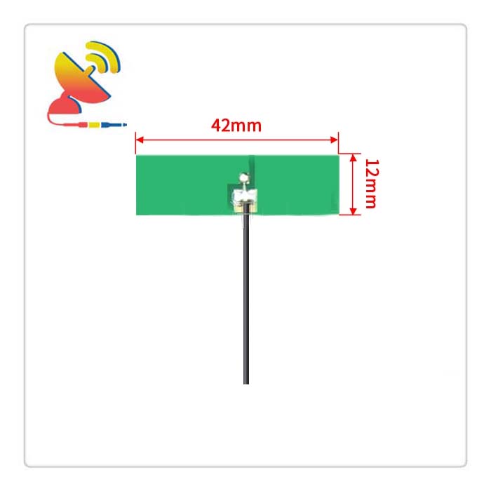
The 802.11 Antenna Wifi 2.4 GHz antenna CTRF-ANTENNA-PCB-2450-4212-IPEX antenna item antenna is an Embedded PCB Antenna with a 42x12mm common size but high-performance PCB board antenna manufactured by C&T RF Antennas Inc. for 802.11 wifi 2.4 GHz ISM applications.
Features of 802.11 Antenna Wifi 2.4 GHz Embedded PCB Antenna
Embedded rigid printed circuit board antenna
2.4 GHz(2400-2500 MHz) band
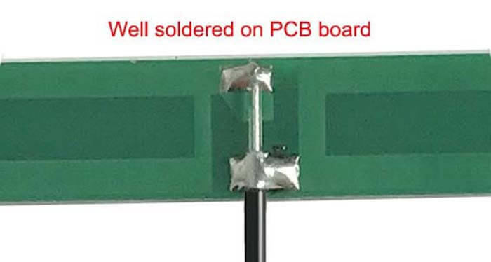
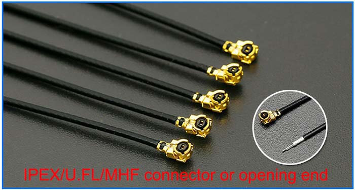
IPEX connector RG 1.13 low-loss cable extension
4dBi gain antenna
For all 2.4 GHz applications such as WiFi/Bluetooth/BLE/Sigfox/Zigbee/Z-wave/ISM, etc
etc.
802.11 Antenna Wifi 2.4 GHz Embedded PCB Antenna Is Available At C&T RF Antennas Inc.
C&T RF Antennas Inc. provides internal & external antennas with the IoT M2M antenna radio frequencies such as NFC, 169MHz, 230MHz, 315MHz, 433MHz, 868MHz, 915MHz, VHF&UHF, Lora, NB-IoT, ADS-B, GSM, GNSS, Wifi 2.4GHz, 5.8GHz, 1.2G, 1.4G, 1.8G, Cellular 2G 3G 4G LTE, GPS, 5G NR, etc.
C&T RF Antennas Inc. provides RF antennae with Omni & Directional antenna types such as Dipole Antennas, Whip Antennas, Marine Antennas, Router Antennas, MIMO Antennas, Combo Antennas, PCB Antennas, FPC Antennas, Spring Antennas, Magnetic Antennas, Sector Antennas, Yagi Antennas, and Accessories, etc, for IoT & M2M industries.
Contact Us For More Info on the 802.11 Antenna such as the 802.11 Antenna datasheet, 802.11 Antenna pricing, 802.11 Antenna inventory, etc.
802.11 Antenna Wifi 2.4 GHz Embedded PCB Antenna Specification
802.11 Antenna Wifi 2.4 GHz Embedded PCB Antenna Electrical Specifications |
|
| RF Antenna Type | Embedded PCB Antenna |
| Model | CTRF-ANTENNA-PCB-2450-4212-IPEX |
| Frequency | 2400-2500 MHz |
| Gain | 4±1dBi |
| VSWR | ≤2.0 |
| Impedance | 50 Ω |
| Polarization | Vertical/Linear |
| Cable Type | RG1.13 |
| Connector | U.FL/IPEX |
| Cable Length | 100mm |
| Lightning Protection | DC-Ground |
802.11 Antenna Wifi 2.4 GHz Embedded PCB Antenna Mechanical Specifications |
|
| PCB Board Dimension | 42*12mm |
| Weight | Approx. 3g |
| Material | PCB |
| Operation Temperature | -40˚C ~ +85˚C |
| Storage Temperature | -40˚C ~ +80˚C |
| Color | Green |
| Antenna Design | Dipole Array |
| Mounting | Connector |
| Safety Emission and other | RoHS Compliant |
| Applications | ISM/SCADA/Utilities, IoT/M2M, WLAN/Wi-Fi/Bluetooth/Zigbee/Sigfox, etc |
802.11 Antenna PCB Antenna Features
802.11 Antenna Applications

PCB Antenna Design
As market competition intensifies, hardware devices are developing in the direction of integration. Antennas have evolved from external to built-in and then embedded. Let’s first introduce the types of antennas for such applications:
⑴ On Board: integrated with PCB etching, limited performance, extremely low cost, used for Bluetooth and WIFI module integration;
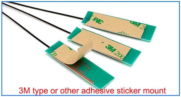
⑵ SMT mounting type: materials include ceramics, metal sheets, and PCBs, with moderate performance and cost, suitable for mass-embedded RF modules;
⑶ IPEX external: using PCB or FPC+Cable combination, excellent performance, moderate cost, widely used in OTT, terminal equipment;
⑷ External external category: plastic rod antenna, high performance, independence, high cost, applied to terminal equipment, no need to consider EMC and other issues;
The ultimate goal of the antenna is to radiate radio frequency signals into free space. At this time, the design of the antenna is very important. However, the antenna design largely depends on the characteristics of the installed platform. In addition, the antenna is very sensitive to the surrounding environment.
In many cases, the antenna is a unique design for each platform. Since the customer is not clear about the factors considered in the antenna design, here are some suggestions for the antenna design of portable devices so that customers can better design their circuits and PCBs and increase the chances of project success.
However each project has its characteristics, so there are still some problems that require specific analysis.
The several forms that the built-in antennas often use are divided into a shrapnel form, a chip patch antenna, and an FPC antenna. The form of the patch antenna is uniform and has a fixed size. The position and size of the pad are also fixed according to the specific specifications of the antenna.
In addition, according to the specific antenna model, there are relevant design guidelines such as the requirements for the clearance around the antenna and the suggestion of equipment size.
If the shrapnel form is adopted, we recommend that customers use a PIFA antenna as the form of a Wi-Fi antenna. According to our experience, the success rate and performance of the PIFA antenna are better.
The size of the antenna RF feed pad should be 2&3mm, and no copper should be placed on all layers of the PCB with an area of ≥0.8mm surrounding the pad. If it is a PIFA antenna, add a 2&3mm ground pad, and the distance between the two pads is 2mm.
The antenna is usually located at the top of the device, starting from the top of the PCB, cut off the ground of all layers in this area by 2 to 3mm, but the pad part of the layer that belongs to the antenna ground pad should be kept.
Reviews
There are no reviews yet.