Description
What is a 2G 3G 4G Broadband Antenna FPCB LTE Antenna?
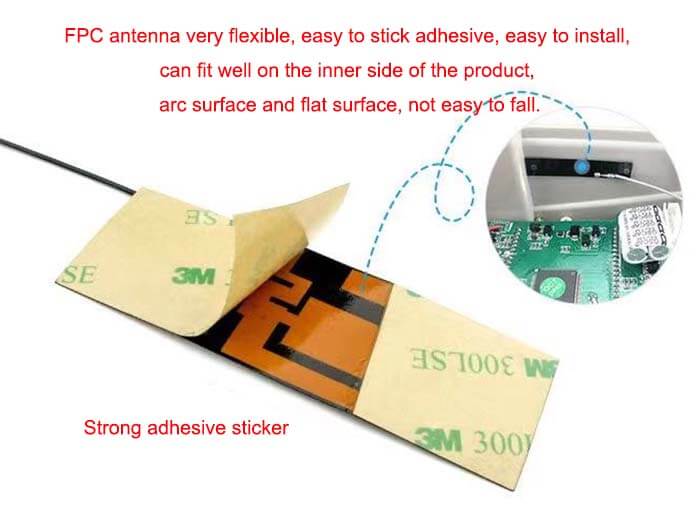
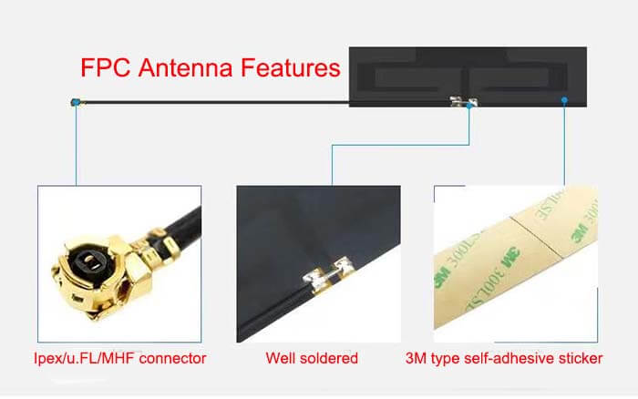
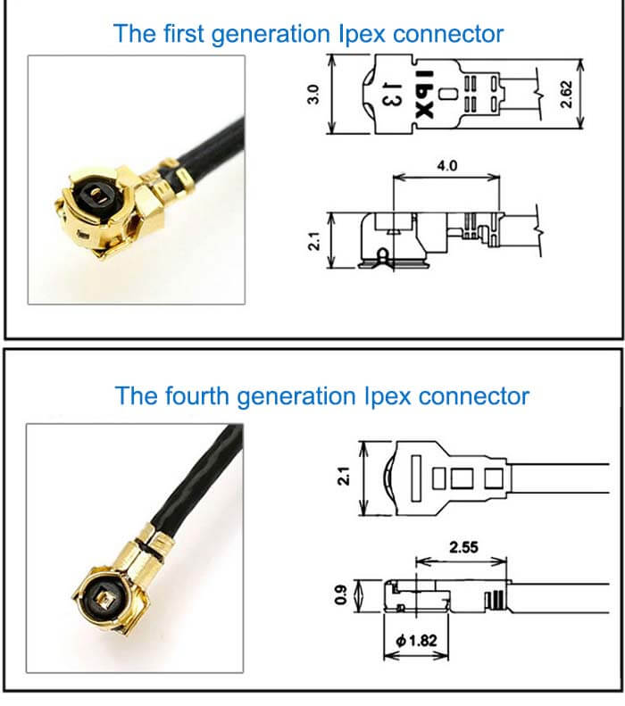
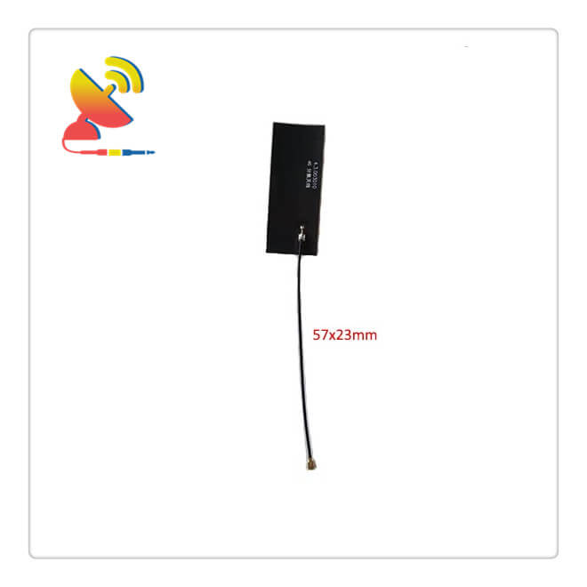
The internal 2G 3G 4G Broadband Antenna CTRF-ANTENNA-FPC-7027-5723-IPEX is a built-in FPC antenna with multiband frequencies 2G 3G 4G Antenna FPCB LTE Antenna manufactured by C&T RF Antennas Inc. It has a 57x23mm flex PCB size and RG 1.13 coax cable 100mm length Ipex/U.FL connector antenna for smart devices.
The 2G 3G 4G Broadband Antenna FPCB LTE Antenna is available at C&T RF Antennas Inc. the indoor and outdoor antenna manufacturer in China.
C&T RF Antennas Inc provides internal & external antennas with the antenna radio frequencies such as NFC, 169MHz, 230MHz, 315MHz, 433MHz, 868MHz, 915MHz, VHF&UHF, Lora, NB-IoT, ADS-B, GSM, GNSS, Wifi 2.4GHz, 5.8GHz, Cellular 2G 3G 4G LTE, GPS, 5G NR, etc.
C&T RF Antennas Inc. provides RF antennae with Omni & Directional antenna types such as Dipole Antennas, Whip Antennas, Marine Antennas, Router Antennas, MIMO Antennas, Combo Antennas, PCB Antennas, FPC Antennas, Spring Antennas, Magnetic Antennas, Sector Antennas, Yagi Antennas, and Accessories, etc, for IoT & M2M industries.
Contact us for more details on the 2G 3G 4G Broadband Antenna FPCB LTE Antenna such as 2G 3G 4G Broadband Antenna datasheet, 2G 3G 4G Broadband Antenna pricing, 2G 3G 4G Broadband Antenna inventory, or other 2G 3G 4G Broadband Antenna styles.
2G 3G 4G Broadband Antenna FPCB LTE Antenna Applications
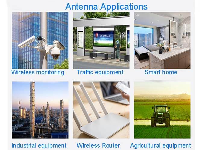
Audio, video, and home appliances
LEDs
Vehicle electronics
Communications network
Medical electronics
Smart grid
Robot
Artificial intelligence
VR|AR|Virtual reality
Wearable device
Safety equipment/system
Military/Avionics
Mobile communication
Portable device
Touch sensing
Internet of Things
Industrial control
2G 3G 4G Broadband Antenna FPCB LTE Antenna Specifications
2G 3G 4G Broadband Antenna FPCB LTE Antenna Electrical Specifications |
|
| RF Antenna Type | Built-In FPC Antenna |
| Model | CTRF-ANTENNA-FPC-7027-5723-IPEX |
| Frequency | 698-960, 1710-2700MHz |
| Gain | 4/6dBi |
| VSWR | ≤2.0 |
| Impedance | 50 Ω |
| Polarization | Vertical Polarization |
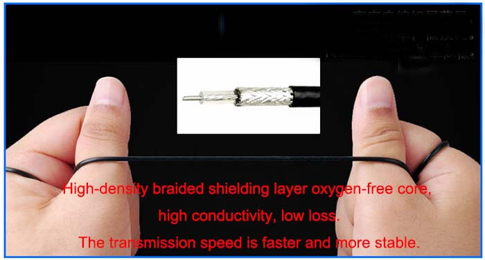
| Cable Type | RG1.13 |
| Connector | U.FL/IPEX |
| Cable Length | 100mm |
| Lightning Protection | DC-Ground |
2G 3G 4G Broadband Antenna FPCB LTE Antenna Mechanical Specifications |
|
| FPC Board Dimension | 57*23mm |
| Weight | Approx. 3g |
| Material | FPCB |
| Operation Temperature | -40˚C ~ +85˚C |
| Storage Temperature | -40˚C ~ +80˚C |
| Color | Black |
| Antenna Design | Dipole Array |
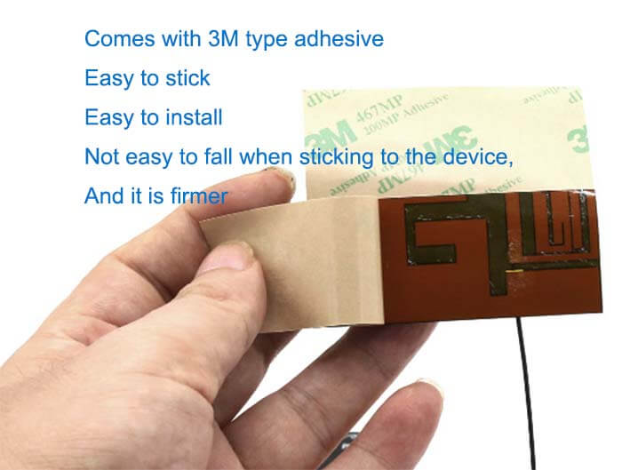
| Mounting | Connector/Peel-and-Stick |
| Safety Emission and other | RoHS Compliant |
| Applications | ISM/SCADA/Utilities, IoT/M2M/NB-IoT/LoRa, 2G 3G 4G LTE/LTE-IoT, GSM GPRS UMTS, etc. |
Flex PCB Antenna Features
Built-in antenna design
In the design of mobile phones, external antennas are gradually being replaced by built-in antennas. The initial concerns about the performance of the built-in antenna are mostly gone.
Facts have proved that in terms of antenna efficiency, which is the most critical electrical parameter for mobile applications, a well-designed internal antenna can provide the same performance as an external antenna.
Consumers’ demand for a more fashionable appearance has further prompted mobile phone manufacturers to integrate antennas inside their devices. SAR (Specific Absorption Rate) was previously considered the biggest problem with built-in antenna phones.
However, the test results show that quite good SAR performance can be achieved in mobile phones with built-in antennas.
Compared with external antennas, internal antennas have the same performance, better appearance characteristics, and more robustness. Therefore, the transition from external to internal antennas has become an irreversible trend.
Antenna performance standards
Almost all of the main equipment types that use built-in antennas use a PIFA (Planar Inverted F Antenna) structure. The performance of this type of antenna mainly includes the following aspects:
● Physical size
● Electrical design quality
● The characteristics of the radio frequency (RF) material of the dielectric substrate and housing (dielectric constant and loss tangent)
● Package and design the entire device
It is very important for system designers to fully understand the characteristics and functions of different built-in antenna technologies early in the product design process. Overly optimistic assumptions about the antenna size will lead to a compromise between packaging and antenna performance.
The built-in antenna of most wireless handheld devices is located above the ground plane of the system and adopts a PIFA structure. A key physical parameter of the mobile phone PIFA is the height of the radiator above the ground plane. At present, most commercial solutions use a height of 7mm to 9mm.
However, it should be pointed out that smart packaging provides the opportunity to minimize this height while maintaining antenna performance (an example of this application is a single-sided circuit board, although it can also be used in some imaginative designs More methods).
Built-in antenna manufacturing technology
The challenge in the future is to integrate the increasingly enhanced functions and bandwidth required for next-generation designs in a compact, cost-effective package. At present, the built-in antennas of wireless handheld devices are usually designed with stamped metal, or use two injections to select a coated plastic structure.
The advantages of stamped metal antennas provide a relatively cost-effective solution. Although the position deviation of the metal contacts to the PCB is a challenge, this method can still integrate a spring that contacts the PCB in the antenna.
Furthermore, the achievable 3D shape of the stamped metal antenna is quite limited, so the physical space in the phone case is not always optimized.
Due to the limitations of stamped metal antennas, some manufacturers choose coated plastic antennas, using two injection molding methods and subsequent electroless plating processes (also called MID devices, molded interconnect devices).
The advantage of this two-shot injection molding technology is that it can produce very complex 3-D shapes so that mobile phone manufacturers can make better use of the space in the mobile phone case. However, the disadvantage of such a coated plastic antenna is that it requires a relatively complicated mold.
Antenna development is an iterative process. In the development of mobile phones, in order to offset mechanical changes or changes in the position of other electronic components, fine adjustments to the antenna are required.
Unfortunately, changing two injection molds is a complicated, time-consuming, and costly process. Moreover, in the production process, this selective plating plastic antenna uses a very slow electroless plating (electroless plating) process, which requires more monitoring and intervention than traditional electrolytic plating.

Reviews
There are no reviews yet.