Description
What is a 50W 2600 MHz LTE Power Amplifier Module?
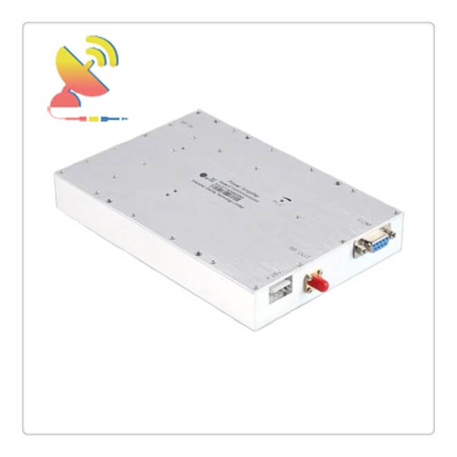
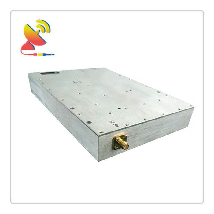
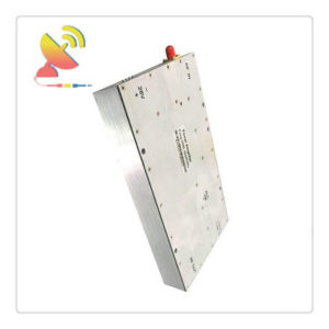
This RF amp module 50W 2600 MHz LTE Power Amplifier Module CTRF-ANTENNA-AMP-PA-2620-2690-50W linear high power amplifier is supplied by C&T RF Antennas Inc and is developed for producing high-frequency energy for LTE applications.
Besides the 50W 2600 MHz LTE Power Amplifier Module, it also can be 60W LTE Power Amplifier Module, 70W LTE Power Amplifier Module, 80W LTE Power Amplifier Module, 90W LTE Power Amplifier Module, 100W LTE Power Amplifier Module, 150W LTE Power Amplifier Module, 200W LTE Power Amplifier Module, 250W LTE Power Amplifier Module, 300W LTE Power Amplifier Module, etc.
The 50W 2600 MHz LTE Power Amplifier Module is supplied by C&T RF Antennas Inc, we provide RF products with RF antennas, Antenna Accessories, Amplifiers, And Repeaters.
C&T RF Antennas Inc provides internal & external antennas with antenna radio frequencies such as NFC, 169MHz, 230MHz, 315MHz, 433MHz, 868MHz, 915MHz, VHF&UHF, Lora, NB-IoT, ADS-B, GSM, GNSS, GPRS, 1.2 GHz, 1.4 GHz, 1.8 GHz, Wi-Fi 2.4 GHz, 5.8 GHz, Cellular 2G, 3G, 3.5 GHz, 4G LTE, GPS, 5G NR, 6G, etc.
C&T RF Antennas Inc. provides RF antennae with Omni & Directional antenna types such as Dipole Antennas, Whip Antennas, Marine Antennas, Router Antennas, MIMO Antennas, Combo Antennas, PCB Antennas, FPC Antennas, Spring Antennas, Magnetic Antennas, Sector Antennas, Yagi Antennas, and Accessories, etc, for IoT & M2M industries.
Contact us for the 50W 2600 MHz LTE Power Amplifier Module price, 50W 2600 MHz LTE Power Amplifier Module specification, and 50W 2600 MHz LTE Power Amplifier Module datasheet.
50W 2600 MHz LTE Power Amplifier Module Specifications:
| Frequency(MHz) | 2620-2690 or Customized |
| Output Power(W) | 47±1(50W ) |
| ALC Range(dB) | ≥25 |
| Gain(dB) | 50 or Customized |
| Gain Adjustment Range(dB) | >30/1dB step or Customized |
| Gain Adjustment Linearity(dB) | ≤±1 |
| Gain Flatness(dB) | ±0.5(Max) |
| Impedance(ohm) | 50 |
| VSWR | ≤1.4:1 |
| Voltage(V) | DC+28 |
| Power Current | ≤5.5A |
| RF Connector | SMA-50K or other Customized |
| Monitor interface | RS-485 or RS232 or other Customized |
| Monitoring communication protocols | Use the Manufacturer’s protocol or Customized |
| Working Temperature | -40~+65 degree |
| Storage Temperature | -55 to +85 degree |
| Operating Humidity | 0 to 90%, relative |
| weight | ≤1.5KG |
| Surface Color | Metal color conductive oxide and other color customized |
| Remark | Module with output short circuit or open circuit protection |
50W 2600 MHz LTE Power Amplifier Module Monitoring Function Description:
| No. | Monitoring function | 50W 2600 MHz LTE Power Amplifier Module Description | |
| 1 | query | PA ALARM | When an alarm amplifier failure |
| 2 | SWR ALARM | Amplifier output reflection is too large, VSWR exceeds3:1, an alarm is generated | |
| 3 | Over-temperature alarm | Module internal temperature exceeds 85 ºC, generates an alarm and turn off the amplifier until the temperature returns to below 65 ºC, re-open the amplifier | |
| 4 | Over-output power alarm | When the output power exceeds the nominal full power2dB is an alarm | |
| 5 | Input power detection | Accuracy of ± 1dB | |
| 6 | Reverse power detection | Accuracy of ± 1dB | |
| 7 | output power detection | Detecting the actual output power amplifier, Accuracy of ± 1dB | |
| 8 | Temperature detection | Detection module operating temperature, detection range: -25 ~ +90 ºC, Accuracy of ± 3 ºC | |
| 9 | SWR | Detecting amplifier output port VSWR range of 1.2 ~ 4.0 | |
| 10 | query and set | PA attenuator Set and query | Set and query the value of ATT |
| 11 | PA switching query and set | Query and set the state open tube amplifier | |
What are the Power Amplifier Types?
Here introduce two types of power amplifiers.
1. RF power amplifier
The radio frequency power amplifier (RF PA) is an important part of various wireless transmitters.
In the front-end circuit of the transmitter, the power of the RF signal generated by the modulation oscillator circuit is very small, and it needs to go through a series of amplification:
A buffer stage, an intermediate amplifier stage, and a final power amplifier stage are to obtain enough RF power before it can be fed Radiate to the antenna.
In order to obtain sufficient RF output power, an RF power amplifier must be used.
RF power amplifier is an important part of transmitting equipment. The main technical indicators of RF power amplifiers are output power and efficiency.
In addition, the harmonic components in the output should be as small as possible to avoid interference with other channels.
2. High-frequency power amplifier
The high-frequency power amplifier is used in the final stage of the transmitting stage.
Its function is to amplify the high-frequency modulated wave signal to meet the transmission power requirements, and then radiate it to space through the antenna to ensure that the receiving stage in a certain area can be a satisfactory signal level received and does not interfere with the adjacent channel communication.
The high-frequency power amplifier is an important component of the transmitting device in the communication system. According to the width of its working frequency band, it can be divided into two types: narrow-band high-frequency power amplifiers and broadband high-frequency power amplifiers.
Narrow-band high-frequency power amplifiers usually use a frequency-selective circuit with frequency-selective filtering as the output loop, so it is also called tuned power amplifier or Resonant power amplifier;
The output circuit of the broadband high-frequency power amplifier is a transmission line transformer or other broadband matching circuit, so it is also called an untuned power amplifier.
The high-frequency power amplifier is an energy conversion device that converts the DC energy supplied by the power supply into a high-frequency AC output.
Amplifiers can be divided into three types of working states: A, B, and C according to the different conduction angles of the current.
The current flow angle of the Class A amplifier is 360o, which is suitable for small signal low power amplification. The current flow angle of the Class B amplifier is approximately equal to 180o;
The current flow angle of the Class C amplifier is less than 180o.
Both Class B and Class C are suitable for high-power work, and the output power and efficiency of the Class C working state are the highest among the three working states.
Most high-frequency power amplifiers work in Class C. However, the current waveform distortion of the Class C amplifier is too large, so it cannot be used for low-frequency power amplification, and can only be used for resonant power amplification with a tuning loop as a load.
Due to the filtering capability of the tuning loop, the loop current and voltage are still very close to the sinusoidal waveform, and the distortion is small.
In addition to the above-mentioned working states classified by current flow angle, there are class D amplification and class E amplification that make the electronic device work in the switch state.
The efficiency of the Class D amplifier is higher than that of the Class C amplifier, theoretically up to 100%, but its maximum operating frequency is limited by the device power consumption (collector dissipation power or anode dissipation power) generated at the moment of switching.
If the circuit is improved to minimize the power consumption of the electronic device at the moment of on-off transition, the operating frequency can be increased. This is the Class E amplifier.
In order to obtain sufficient low-frequency output power in the low-frequency amplifier circuit, a low-frequency power amplifier must be used, and the low-frequency power amplifier is also an energy converter that converts the energy provided by a DC power supply into an AC output.
The common characteristics of high-frequency power amplifiers and low-frequency power amplifiers are large output power and high efficiency, but the working frequency and relative bandwidth of the two are quite different, which determines the essential difference between them.
The working frequency of the low-frequency power amplifier is low, but the relative frequency bandwidth is very wide. For example, from 20 to 20000 Hz, the ratio of high to low frequency reaches 1000 times.
Therefore, they all use untuned loads such as resistors and transformers. The working frequency of the high-frequency power amplifier is high (from hundreds of kHz to hundreds, thousands, or even tens of thousands of MHz), but the relative frequency band is very narrow.
For example, the bandwidth of an AM broadcasting station (the frequency range of 535-1605 kHz) is 10 kHz. If the center frequency is 1000 kHz, the relative bandwidth is only one-hundredth of the center frequency.
The higher the center frequency, the smaller the relative bandwidth. Therefore, high-frequency power amplifiers generally use frequency-selective networks as load loops.
Because of this latter feature, the working conditions of these two amplifiers are different:
The low-frequency power amplifier can work in Class A, Class A, and Class B or Class B (limited to push-pull circuits);
High-frequency power amplifiers generally work in Class C (in some special cases, they can work in Class B).
Each intermediate stage of the broadband transmitter also widely uses a new type of broadband high-frequency power amplifier, which does not use a frequency-selective network as a load loop but uses a transmission line with a wide frequency response as a load.
In this way, it can change the operating frequency in a wide range without re-tuning.
In summary, it can be seen that the common point of the high-frequency power amplifier and low-frequency power amplifier is that it requires high output power and high efficiency;
The difference between them is that their working frequency and relative bandwidth are different, so the load network and working state are also different.
The main technical indicators of the high-frequency power amplifier are:
Output power, efficiency, power gain, bandwidth and harmonic suppression (or signal distortion), etc.
These index requirements are contradictory. When designing an amplifier, some indexes should be highlighted and other indexes should be taken into consideration.
For example, in some circuits in practice, preventing interference is the main contradiction, and requires higher harmonic suppression, while the bandwidth requirements can be appropriately reduced.
The efficiency of the power amplifier is a prominent problem, and its efficiency is directly related to the working state of the amplifier. The working state of the amplifier can be divided into Class A, Class B, and Class C.
In order to improve the working efficiency of the amplifier, it usually works in Class B and Class C, that is, the transistor operation extends to the nonlinear region.
However, there are serious nonlinear distortions between the output current and output voltage of the amplifier under these working conditions.
The low-frequency power amplifier cannot use the resonant circuit as the load because of the large frequency coverage coefficient of its signal, so it generally works in the Class A state;
It can work in Class B when using the push-pull circuit. High-frequency power amplifiers can use resonant circuits as loads due to their low signal frequency coverage. Therefore, they usually work in Class C.
Through the frequency selection function of resonant circuits, harmonic components in the amplifier collector current can be filtered out and selected The fundamental component thus basically eliminates nonlinear distortion.
Therefore, high-frequency power amplifiers have higher efficiency than low-frequency power amplifiers.
Because high-frequency power amplifiers work in the nonlinear state of large signals, linear equivalent circuit analysis cannot be used.
In engineering, analytical approximate analysis methods are generally used to analyze their working principles and working conditions.
The physical concept of this analysis method is clear, and the analysis work status is convenient, but the calculation accuracy is low.
Among the various types of high-frequency power amplifiers discussed above, narrow-band high-frequency power amplifiers:
It is used to provide sufficiently strong narrow-band signal power centered on the carrier frequency, amplify narrow-band modulated signals, or realize the function of frequency multiplication. It usually works in Class B and Class C states.
Broadband high-frequency power amplifier:
It is used for the wide range of frequency variations of some carrier signals, such as short-wave and ultra-short-wave radio stations. It usually works in Class A status.
Reviews
There are no reviews yet.