UWB technology is the best and most advanced positioning technology available today, and why?
This chapter explores the inner workings of UWB technology and provides an overview of the differences between UWB technology and narrowband positioning methods. In addition, the chapter explains how to select the best system architecture for different applications or use case scenarios.
UWB technology is compared to narrowband
There are a variety of technologies for indoor and outdoor positioning applications, but UWB technology is the most accurate, reliable, and cost-effective; it is also often more scalable. This is clearly illustrated by comparing UWB technology with the most popular narrowband methods, which is what we will do in this section.
All positioning techniques depend on bandwidth
From the beginning, pulse radio UWB technology was designed to achieve high accuracy range estimation while communicating in both directions. This allows it to collect sensor data and control actuators.
Pulse Radio is a form of UWB signal whose characteristics make it ideal for positioning and communication services in dense multipath environments.
In addition to its positioning capabilities, Qorvo UWB technology is compliant with the IEEE 802.15.4a standard and the recently released IEEE 802.15.4z standard.
In addition to centimeter-level ranging accuracy, developers emphasized the need to ensure that the technology is stable and immune to all types of interference, resulting in greater reliability.
The standard was also developed with low power consumption and low cost in mind, as well as the ability to support a large number of interconnected devices. Engineers created the standard with a vision to make every interconnected object location-aware.
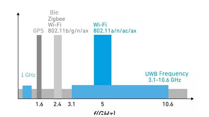
The Federal Communications Commission (FCC) defines the UWB radio frequency range as 3.1 GHz to 10.6 GHz, with a minimum signal bandwidth of 500 MHz. unlike other radio technologies, UWB technology does not use amplitude or frequency modulation to encode the information its signals transmit.
Instead, UWB technology uses very narrow sequences of short pulses to encode data using binary phase-shift keying (BPSK) and/or pulse-position modulation (BPM). The use of narrow pulses results in transmissions that exhibit wide-bandwidth characteristics, allowing for extended range, reduced sensitivity to narrowband interference, and the ability to operate in the presence of multi-path reflections.
Limitations of RSSI
In many of today’s applications, location tracking is implemented using Received Signal Strength Indicators (RSSI). In RSSI applications, the strength of the radio signal varies inversely with the square of the distance from the transmitter in free space. As the signal moves away from the source, the signal strength decreases.
Use RSSI in conjunction with Wi-Fi and Bluetooth 802.11 standards. The distance between devices can be predicted based on the known transmit power of the device at the transmitter. However, there are drawbacks to these types of measurements, which we discuss next.
Location tracking using Bluetooth
Bluetooth location tracking, such as Bluetooth Low Energy (BLE) beacons, can be effective in some cases. Beacons are primarily used for proximity detection. They detect when a device (such as a phone) is in coverage and estimate the distance by differentiating the strength of the signal strength (RSSI).
The problem with this method is that the signal strength is not a good reflection of the distance. If the signal strength is low, does it mean that the phone is far from the beacon, or does it mean that there is a huge column between the beacon and the phone? The line of sight (LOS) between each beacon and the receiving phone can be good or bad; each obstruction can change the overall accuracy of the distance measurement.
Device A can receive a very strong signal from the beacon on the ceiling of the conference room, but the wall makes the signal significantly weaker from the beacon in the corner near the outside of the conference room, and both beacons are at approximately the same distance from Device A.
Device B is not within the LOS of any of the beacons, so all signals are significantly weaker, while Device C is within the LOS of multiple beacons in the open office. So the signal strength is stronger because there is less attenuation.
A workaround to this problem is to use a method called fingerprint recognition.
The signal strength of other beacons at known locations is first measured using a beacon mounted at a fixed location a few meters away. This signal strength information is stored in a fingerprinting database.
The beacon then determines the distance and location of the device by comparing its signal strength with the data in the fingerprint recognition database. The position measurement is obtained based on the closest match.
There are many versions of fingerprint recognition and they use a variety of complex algorithms. Keep in mind that these systems are only workarounds. They don’t really solve the distance measurement problem with the accuracy of technologies like UWB.
Location tracking using Wi-Fi
Wi-Fi is the most commonly used radio signal for indoor positioning applications. It remains the most widely used indoor positioning technology and is often used in combination with BLE. The main advantage of Wi-Fi is that it is available in most public or private locations.
However, using Wi-Fi signal strength to estimate distances can face the same challenges as Bluetooth. Some companies have developed alternative algorithms that attempt to use the time of flight (ToF) or time of arrival (ToA) of Wi-Fi signals to more accurately measure distance, but this cannot be achieved directly using standard Wi-Fi hardware.
ToF is a method of measuring the distance between two radio transceivers by multiplying the signal’s ToF by the speed of light. ToA is the point in time when the radio signal reaches the remote receiver from the transmitter.
The accuracy of RSSI fingerprinting can be improved to some extent by adding more beacons to the network. While the accuracy may improve a little, it does not improve the overall reliability of the measurement. In addition, the fingerprinting database would need to be updated if there were any changes to the floor plan, which can be both costly and time-consuming.
Why is UWB technology best suited for indoor location tracking?
The inherent characteristics of UWB technology mean that it allows for more accurate indoor positioning and distance measurement than other technologies.
UWB technology pulses are only 2 nanoseconds (ns) wide, so they are unaffected by reflected signal (multipath) interference and noise, and UWB radio frequency (RF) pulses have sharp edges, so arrival times and distances can be accurately determined despite the signal reflections and multipath effects common in everyday environments.
When UWB technology is used as a solution, the reflected signal does not affect the direct signal. IR-UWB signals have shorter rise and fall times than standard narrowband signals, so the arrival time of the signal can be accurately measured.
This also helps the UWB signal maintain its integrity and structure in the presence of noise and multipath effects.
Even under noisy conditions, the arrival time of a 2-ns-wide pulsed radio UWB pulse is virtually unaffected. In contrast, narrowband signals are more significantly affected by noise.
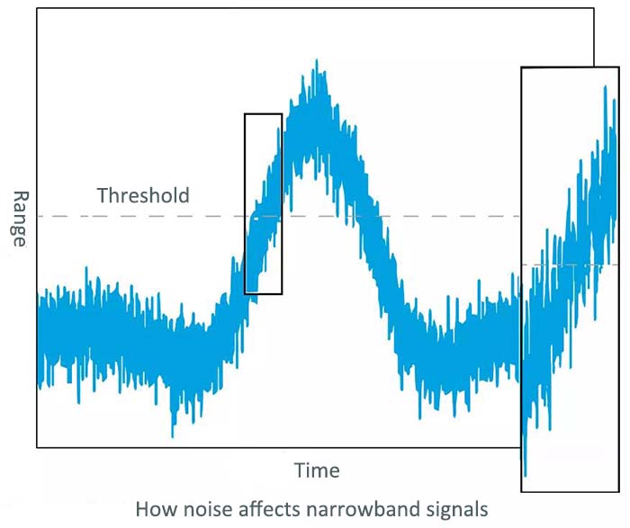
We have tested the ToF-based approach using narrowband radio technology. Narrowband signals are very sensitive to multipath because the reflected signal can combine destructively with the direction via a signal to generate the final signal at the receiver end. This affects the time it takes for the signal to exceed the threshold (used to measure ToA), thus reducing accuracy.
The accuracy advantage of UWB technology is clear: UWB technology is fully capable of measuring distance and position with an accuracy of 5 to 10 centimeters. In contrast, Bluetooth, Wi-Fi, and other narrowband radio standards can only achieve meter-level accuracy.
In addition, because of the extremely short radio pulses of UWB technology, direct path signals do not overlap with multipath signals due to multipath effects, thus not compromising signal integrity and strength.
This demonstrates that UWB technology has the following properties.
Ultra-accurate, providing centimeter-level accuracy that is 100 times more accurate than BLE and Wi-Fi
Ultra-reliable, maintaining signal integrity in the presence of multipath reflections
Real-time, with latency 50 times lower than global positioning systems (GPS) and 3,000 times lower than standard beacons
What are the system components of UWB technology, and how do hardware and software choices affect system performance?
Anchor Points and Tags for UWB Technology
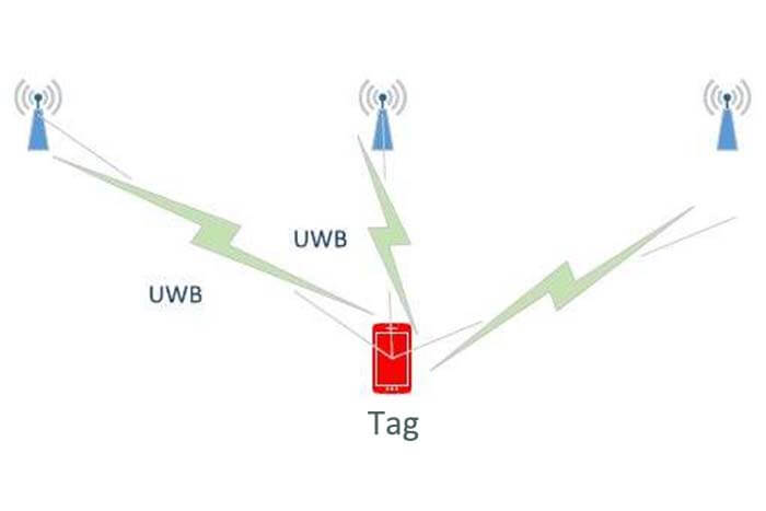
To understand UWB technology systems, you need to understand the terms anchor and tag.
An anchor point is usually a fixed UWB device. A tag is usually a mobile UWB device. Anchor points and tags exchange information in order to determine the distance between them. The exact location of the tag can be determined by communicating with multiple anchors.
Some devices can act as both anchors and tags. For example, when two cell phones use UWB to calculate the distance between each other, they can switch roles in the calculation process, alternately serving as tags and anchors.
Storage Units and Processing Power
Typical UWB devices require a certain level of processing power and specific functionality. For simple tags, the processor is required to have a small amount of flash memory (programmable non-volatile memory) and data memory (volatile random access memory, or RAM).
For anchor point applications, such as those used in Time Difference of Arrival (TDoA), processors with more flash and RAM, and in many cases, data return may be required.
For anchor points, different types of processors may be required, depending on system size and workload/throughput requirements.
UWB Antennas
Another system consideration is the UWB antenna. Different applications will require different antennas. For example, tags typically use small omnidirectional antennas. Anchor points, on the other hand, may want to use directional antennas, depending on the topology.
UWB Software Stack
An important interconnection between UWB communication components and applications is the UWB software stack. The software stack helps coordinate interoperability and coexistence with external devices.
In addition, the software enables the communication between UWB communication components and internal microcontrollers. For example, the software is responsible for coordinating communications when controlling the connection between a smartphone and a car.
The software can also manage multiple applications and use cases simultaneously. For example, a solution may be part of a smart home ecosystem that controls speakers, lighting fixtures, heating systems, etc.
It can communicate with all UWB tags and UWB-enabled devices while using location information to control the environment, lock, and open doors, enable and disable alarm systems, etc. The UWB software stack can handle all of these different scenarios simultaneously.
Using the UWB software stack ensures that UWB communication components meet the needs of different applications. In addition, taking advantage of the software’s many features can make things easier from both an end-user and overall system design perspective.
UWB Technology Function Prioritization
In some application scenarios, different functions need to be prioritized. For example, suppose that power management and battery life are important in an application, more so than location update rate or data throughput.
In this case, the software can be used to optimize power consumption by setting the device to turn off when not in use and when communication is needed.
Another scenario is when the sensor LOS signal is not ideal or is coming from a different direction. In this case, the software can be used to average the results to obtain accurate distance information; it can also smooth out signals that are noisier than others.
For more accurate results, especially in fast-moving applications, or to add information about device orientation, the software can also integrate data from the UWB technology chipset with data from inertial measurement devices, including accelerometers, gyroscopes, magnetometers, etc.
UWB Topology Comparison and Selection
UWB technology utilizes the concept of ToF, which is a method of measuring the distance between two radio transceivers by multiplying the ToF of the signal by the speed of light. Based on this basic principle, UWB positioning techniques can be implemented in different ways depending on the needs of the target application.
The optimal topology is largely determined by the application. This means that the design engineer must first match the application to the topology. The options available are Two-Way Ranging (TWR).
The TWR method calculates the distance between the tag and the anchor by measuring the ToF of the UWB RF signal and then multiplying that time by the speed of light.
An example of an application using the TWR method is an automotive keyless access control system TWR generates a secure space, similar to a security bubble while ensuring that this bubble maintains high precision security control at the time of application.
If you implement a TWR scheme between two devices, you can obtain information about the distance between the devices. On top of the TWR scheme, you can also implement 2D or even 3D position measurement between a moving tag and a fixed anchor point; called the trilateral measurement method.
With the TWR method, three messages can be exchanged. The tag initiates TWR by sending a polling message with a known anchor address; the anchor records the poll reception time and replies with a response message. After the response message is received, the tag records the time and writes the last message. The anchor can use the information in the last message to determine the ToF of the UWB signal.
Time Difference of Arrival (TDoA) and Reverse TDoA of UWB technology
TDoA and reverse TDoA methods are similar to GPS. Multiple reference points, called anchor points, are deployed at known fixed locations, and these anchor points are closely synchronized in terms of time.
In the case of TDoA, the mobile device will blink (i.e. send information periodically) and when the beacon signal is received by the anchor point, it will mark the timestamp based on a common synchronized time base.
The timestamps of multiple anchor points will then be forwarded to the central positioning engine, which will run a multi-point positioning algorithm based on the TDoA of the beacon signal for each anchor point. Finally, the 2D or 3D position of the mobile device is obtained.
Reverse TDoA is more like GPS, in which anchor points send synchronized beacons (with fixed/known offsets to avoid collisions) and the mobile device uses TDoA and multi-point positioning algorithms to calculate its position.
The phase difference of arrival (PDoA)
Another UWB topology is PDoA. PDoA can combine the distance between two devices with an orientation measurement between them.
Using the combined distance and bearing information, the relative positions of the two devices can be calculated without any other infrastructure.
For this purpose, one of the devices must be equipped with at least 2 antennas and be able to measure the phase difference of the arriving signal carriers at each antenna. The phase is completely independent of the antenna distortion and measurement accuracy of better than 10° can be achieved, allowing the determination of the transmitter’s orientation in less than 5°.
For each topology, which application is best suited? The use cases focus on three different areas: inductive access control, location services, and device-to-device (point-to-point) applications.
Besides the How Does UWB Technology Work article, you may also be interested in the below articles.
What is the difference between WIFI and WLAN?
Summary of 41 Basic Knowledge of LTE
What Is The 5G Network Slicing?