What is RF antenna impedance matching?
Impedance is an important parameter of the antenna, of the shape, size, material, use environment, and other physical structures of the antenna decision. RF antenna impedance matching is the process of matching the antenna impedance with the transmitter source impedance through tuning.
Usually, the antenna impedance matching on a certain frequency point of the antenna can be done by using the SMITH circle diagram tool, two devices can surely get it done, that is, by connecting the inductor or capacitor in series + parallel can realize the antenna impedance matching from any point on the circle diagram to another point, but this is single frequency.
And the cell phone antenna is dual-band, matching one of the frequency points, will certainly affect the other frequency points, so antenna impedance matching can only be a compromise between the two bands.
At a frequency point matching is easy, but above the dual-band antenna is more complicated. Because in 900MHz completely matched, then 1800MHz will not reach match.
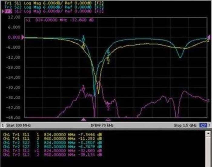
To calculate a suitable matching circuit, it is best to use simulation software or a point matching well, in the network analyzer under the S11 parameters to adjust, because the dual-band matching point is certainly not too far from here, only two components matching is unique, but pi-type network matching, there are countless solutions. At this point, simulation is needed to pick, and it is best to have experience using it.
Simulation tools are of little use in the actual process. Because the simulation tool does not know the model of your component. You have to enter the model of the actual component, meaning the various distribution parameters, for your results to match the actual.
An actual inductor is not something that can be measured simply by inductance; it should be an equivalent network to simulate.
In actual design, it is important to fully understand the principle of Smith’s circle diagram, and then use the network analyzer’s circle diagram tool to debug more. Knowing the principle lets you qualitatively know what pieces to use, and more tuning to familiarize you with how the components you use will move on the actual circle diagram.
Due to the distribution parameters and the different frequency response characteristics of the components, the actual pieces on the circle diagram and your theoretical calculation of the movement will be different.
The antenna impedance matching of dual frequencies is indeed a compromise process. You must have a purpose in adding a piece. In the case of GSM and DCS dual-band, if you want to tune GSM and don’t really want to change DCS, you should choose to connect capacitors in series and inductors in parallel. Similarly, if you want to tune DCS, you should choose a series inductor and parallel capacitor.
Theoretically, you need 2 pieces to tune a frequency point, so the actual cell phone or mobile terminal usually arranges the matching circuit according to the following rule.
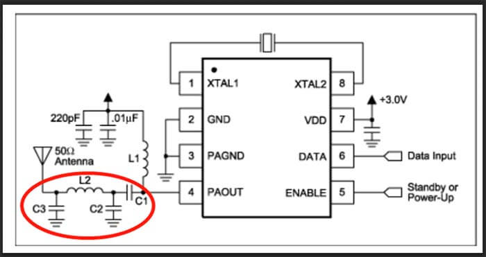
For some simple, antenna space is relatively large, the reflection would have been smaller, using Pai types (2 and a string), such as conventional straight plate cell phones, and conventional flip-cover machines.
Slightly more complex using double L type (2 series and 2 parallel): for more complex, using L + Pai type (2 series and 3 parallel), such as cell phones UHF & VHF rubber duck antenna.
Remember, an antenna impedance matching circuit can reduce the reflection, but at the same time will introduce loss. In some cases, although the VSWR is good, the efficiency of the antenna system will be reduced instead. So the design of matching circuits is somewhat taboo.
For example, in GSM, UMTS cell phone antenna impedance matching circuit, series inductance is generally not greater than 5.6nH. Also, when the antenna reflection itself is relatively large, bandwidth is not enough, in the smith diagram to see the boundary points of each band from the center of the circle radius is large, generally adding matching is not improve the radiation.
The reflection index of the antenna (VSWR, return loss) in the design process is generally just a reference. The key parameters are the transmittance parameters (such as efficiency, gain, etc.).
Some people really emphasize return loss, which must be -10dB, and VSWR should be less than 1.5, in fact, there is no meaning.
SWR standing wave ratio only shows the matching degree of the port, that is, the degree of antenna impedance matching. Matching good, SWR small, the antenna input port reflected back to the power small. Matching is not good, the reflected power is back to the big. As for the part of the power into the antenna that is not radiated, you are not clear.
The efficiency of the antenna is the ratio of the total power radiated into space to the total power at the input port. So SWR is good, can not judge the antenna efficiency must be high (take a 50ohm matching resistor connected, SWR is good, but there is radiation?).
But SWR is not good, the reflected power is big, and you can be sure that the antenna efficiency must not be high.SWR good is the necessary but not sufficient condition for antenna efficiency.SWR good and radiation efficiency (radiation efficiency) high is the sufficient necessary condition for antenna efficiency.
When SWR is the ideal value (1), the port ideal match, then the antenna efficiency is equal to radiation efficiency.
In today’s cell phones, the space of the antenna is compressed smaller and smaller, at the expense of the performance of the antenna as the price. For some multi-band antennas, even VSWR reached 6.
Previously, we use more external antennas, and the average efficiency of 50% is considered low, now more than 50% of the efficiency is even very good!
Take a look at the market of cell phones, even if the company’s name, such as Nokia, also efficiency is less than 20%. Some cell phones (slider ah, rotating ah) and even some frequency points of efficiency of only 10% or so.
Seen several cell phone built-in antenna test reports, and antenna efficiency is basically about 30-40%, their actual engineering, seems to be due to the S11 loss and matching circuit loss in the efficiency.
According to the antenna principle, only the dielectric loss (including those caused by the substrate and the magnet inside the phone) and metal loss (although very small) is in the antenna loss, and the return loss and matching circuit loss should not be credited.
But engineering is engineering, so easy to test it.
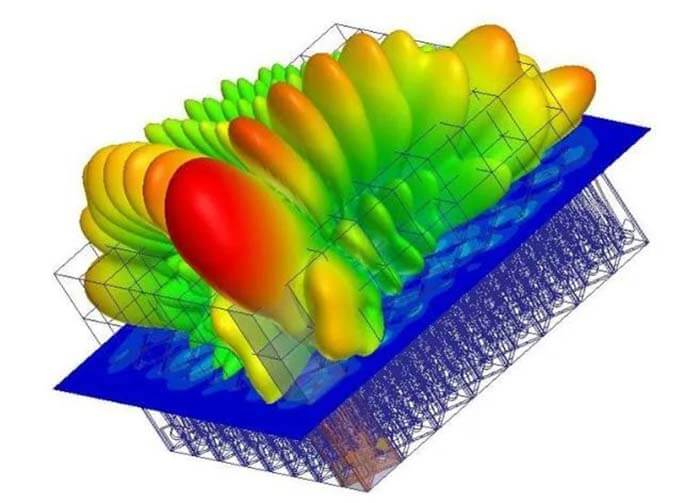
Add other sentences, software simulation to a certain degree is helpful to the project. Of course, the accuracy of the simulation results can not be compared with the test, but the parameter scan simulation to obtain the trend of antenna performance with the parameters is still useful, which is much faster than the test to obtain data, especially for some of the less common parameters.
Simulation tools are of little use in practical engineering, which means when designing antenna impedance matching circuits, more specifically when designing dual-band GSM and DCS cell phone antenna impedance matching circuits.
If this statement is understood alone, it is undoubtedly wrong. In fact, we have been using HFSS for antenna simulation, the results are also based on the simulation results.
In the actual design, there is another situation you can’t consider in the simulation (unless you measure it beforehand). That is the effect of distribution parameters on PIFA.
Since antenna heights are getting smaller these days, and antenna impedance matching circuits are either below (inside) or above (outside) the antenna, very close anyway, adding an actual component introduces changes in the distribution parameters in practice.
Especially if the board layout is not good, this effect will be more obvious. The actual soldering, or even if a piece is not well soldered and re-soldered a bit, can bring about changes in impedance.
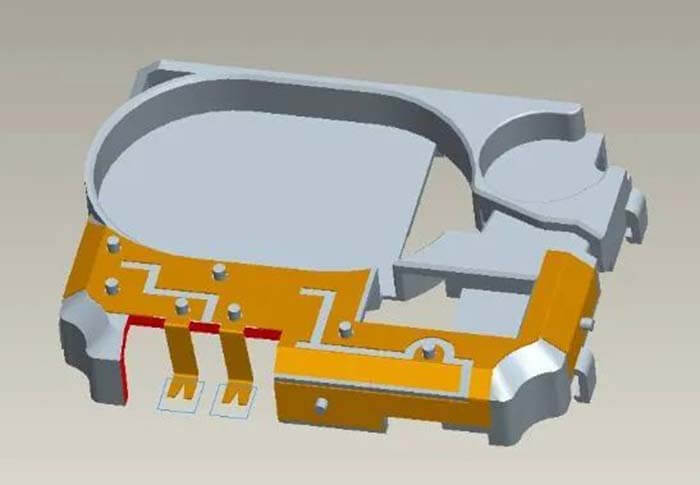
Therefore, in the PIFA antenna design, we usually do not use an antenna impedance matching circuit (or called 0-ohm matching). This requires you to carefully adjust the optimization of your antenna.
Generally speaking today’s flexible printed circuit board design solutions (Flexfilm-FPC) is easier to do, because it is easier to modify the radiation sheet.
For the more used antenna design scheme stamping metal sheet, relatively speaking, is more difficult.
First, the hardness of the process can not be fully justified by the limitations of all the space, the second is the mold once formed modifying the design of the radiation sheet is also very difficult.
In the antenna impedance matching design simulation tools have no great use, not many people are able to use simulation tools to calculate the match.
How do you consider the change in the distribution parameters of the PIFA match I mentioned above? Before I also mentioned some antenna impedance matching circuit taboos, not from theory, but completely from practice. Because the antenna is designed with the hope to improve its radiation efficiency (total efficiency)!
When dealing with the practical application of RF systems, there is always some very difficult work, and matching the different impedances of each part of the cascade circuit is one of them.
In general, the circuit that needs to be matched includes matching between the antenna and the low noise amplifier (LNA), matching between the power amplifier output (RFOUT) and the antenna, and matching between the LNA/VCO output and the mixer input. The purpose of matching is to ensure that the signal or energy is efficiently transmitted from the signal source to the load.
At the high-frequency end, parasitic components (e.g. inductors on connecting lines, the capacitance between board layers, and resistance of conductors) have a significant and unpredictable effect on the matching network.
At antenna frequencies above tens of megahertz, theoretical antenna calculations and simulations are no longer sufficient, and RF tests performed in the laboratory with proper tuning must also be taken into account in order to obtain appropriate final results.
The antenna calculated values are needed to determine the type of circuit construction and the corresponding target component values.
What are the antenna impedance matching methods?
There are many methods of antenna impedance matching, including 4 types of antenna impedance matching.
RF antenna impedance matching 1) Computer simulation.
Since this type of software is designed for different functions and not just for impedance matching, it is more complex to use. The designer must be familiar with entering numerous data in the correct format. The designer also needs to have the skills to find useful data from a large number of output results.
In addition, circuit simulation software cannot be pre-installed on a computer unless the computer is made specifically for this purpose.
RF antenna impedance matching 2) Manual calculation.
This is an extremely tedious method because it requires the use of long (“kilometers”) formulas and the data being processed are most complex.
RF antenna impedance matching 3) Experience.
Only people who have worked in the RF field for many years can use this method. In short, it is only suitable for senior experts.
RF antenna impedance matching 4) Smith’s circle diagram.
Besides this About RF Antenna Impedance Matching article, you may also be interested in the below articles.
What is the difference between WIFI and WLAN?
Summary of 41 Basic Knowledge of LTE
What Is The 5G Network Slicing?