Description
What is Variable RF Attenuator?
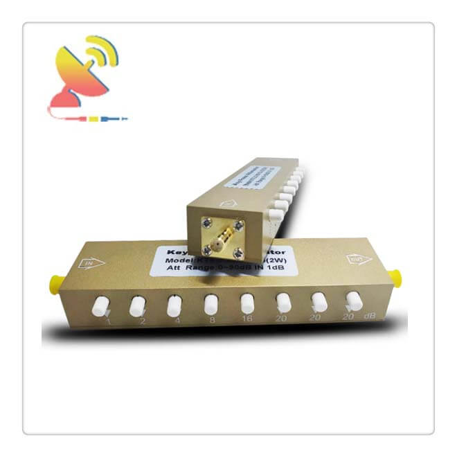
Variable RF Attenuator Variable attenuators, like the name suggests, are attenuators whose attenuation amplitude can be changed by varying the voltage/current or turning a knob.
The Variable RF Attenuator is the Key-press attenuator variable attenuator, Variable RF Attenuator can be SMA female connector variable attenuators or N-Type variable attenuators.
The Variable RF Attenuator is available at C&T RF Antennas Inc. To contact us for the Variable RF Attenuator’s datasheet, Variable RF Attenuator pricing, and Variable RF Attenuator inventory.
Variable RF Attenuator Product parameter
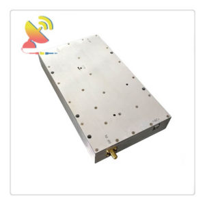
KT2.5-90/1S-2S stepping coaxial attenuator
As the in-camera attenuator of the instrument and equipment, used to adjust the power level in the test system
Working frequency: DC-3.0GHz
Insertion loss: ≤3dB
Standing wave ratio: ≤1.5
Rated power: 2w
Weight: 150g
Connector form: SMA-F
Attenuation adjustment range: 0-90dB step
Dimensions: 149X20×35.5mm
Attenuation step: 1, 2, 4, 8, 16, 20, 20, 20 (dB)
Temperature range: -10°℃+50°℃(operating); -40°℃~+70℃(not operating)
Single key attenuation accuracy: ±0.9dB Max (0~8dB) ±2.0dB Max (10~20dB)
Multi-key attenuation accuracy: ±3.5dB Max
Variable RF Attenuator Specifications
N-type/SMA button adjustable attenuator 0-90dBN double female RF attenuator signal power attenuator
2W SMA-KK 0-30dB 0-3G & 2W N-Type-KK 0-30dB 0-3G
2W SMA-KK 0-60dB 0-3G & 2W N-Type-KK 0-60dB 0-3G
2W SMA-KK 0-90dB 0-3G & 2W N-Type-KK 0-90dB 0-3G
2W SMA-KK 0-60dB 0-4G & 2W N-Type-KK 0-60dB 0-4G
2W SMA-KK 0-90dB 0-4G & 2W N-Type-KK 0-90dB 0-4G
2W SMA-KK 0-35dB 0-5G & 2W N-Type-KK 0-35dB 0-5G
5W SMA-KK 0-30dB 0-3G & 5W N-Type-KK 0-30dB 0-3G
5W SMA-KK 0-60dB 0-3G & 5W N-Type-KK 0-60dB 0-3G
5W SMA-KK 0-90dB 0-3G & 5W N-Type-KK 0-90dB 0-3G
5W SMA-KK 0-35dB 0-5G & 5W N-Type-KK 0-35dB 0-5G
10W SMA-KK 0-30dB 0-3G & 10W N-Type-KK 0-30dB 0-3G
10W SMA-KK 0-60dB 0-3G & 10W N-Type-KK 0-60dB 0-3G
10W SMA-KK 0-90dB 0-3G & 10W N-Type-KK 0-90dB 0-3G
10W SMA-KK 0-90dB 0-4G & 10W N-Type-KK 0-90dB 0-4G
Types and functions of RF attenuators
In RF circuits, higher signal levels are usually a good thing. They can improve the signal-to-noise ratio (SNR) and reduce problems caused by internal circuit component noise and external signal noise. As a result, higher signal levels often simplify many of the challenges of RF circuit design.
However, in many systems, RF signals inevitably have a wide dynamic range spanning 30, 40, or more dB; some designs must handle signals with a range exceeding 100 dB.
Examples include radar or long-range wireless, or even short-range LAN, where one or two link nodes are moving and there are obstacles and interference.
If the system is designed to work normally with lower-level signals, there may not be a margin for higher-power signals (RF, power, and signal level are usually closely related).
The result is overload, saturation and may even damage sensitive analog components, such as front-end amplifiers. Even if there is no permanent damage, as long as the components of the signal chain are maximized, the system will not work properly.
In these cases, it may take a relatively long time for the component to get out of the saturation chain and become feasible again. In other cases, the attenuator matches the maximum value of the signal at one point with the maximum value of the larger limit at another stage in the chain.
For these reasons, it is often necessary to manage and attenuate the signal level. With known or controllable quantities, this is where the RF attenuator comes into play. There are three types of RF attenuators.
1) Fixed value attenuator, providing one or two dB, or 10 dB, 20 dB, or more dB value.
2) Voltage variable or voltage controlled attenuator, where the analog voltage is set at the attenuation level within a continuously variable range, for example, between 0 dB and 30 dB or between 0 dB and 60 dB.
3) Digital controlled attenuator or digital step attenuator (DSA), where a multi-bit code establishes attenuation in discrete steps from 0 dB to 32 or 64 dB, for example, in steps of 1 or 2 dB/bit Long; some products provide steps as small as 0.25 dB.
(Please note that there are also mechanically controlled attenuators, users can set the attenuation through the knob. These attenuators are almost only used in test environments or high-power one-off designs.)
The controllable attenuator is a complement to the variable gain amplifier (VGA), which can enhance the signal to match the range of components in the chain.
For designs that require additional flexibility, there are even available VGAs that can span gain and attenuation, such as -10 to +40 dB; internally, these are variable attenuators (voltage or digital control) in series with gain modules Constructed.
It seems reasonable to simply use a variable attenuator instead of a fixed attenuator to provide maximum flexibility.
However, this flexibility comes at a price, because variable attenuators are more costly, dissipate more power, and require (in most versions) control signals at power-up, as well as continuous supervision and management during use.
These are additional burdens on the system processor and initialization process. In contrast, apart from installing it, it has nothing to do with the fixed attenuator.
In other cases, “fixed” attenuators are designed to provide a controlled temperature coefficient to stabilize high-power RF amplifiers when operating temperature changes.
Key attenuator parameter guide selection
Like all components, attenuators have many design specifications that define their applicability in a given application. The main part of the attenuator is the frequency range and attenuation value.
Some attenuators are designed and designated for relatively wideband use, such as 1 to 4 GHz, while others are for narrowband situations, such as the nominal 2.4 GHz ISM band.
Although wider bandwidth seems to be a benefit, it is more costly to design and implement performance on a wider frequency band.
A similar situation exists with variable attenuators. A wide-range unit operating in a range above 30 dB is more expensive than operating in a range above 30 dB.
The two parameters of frequency range and attenuation are combined with other key specifications: attenuation deviation or flatness within the frequency range and the entire operating temperature range.
Flatness is usually on the order of 0.25dB or 0.5dB and is usually difficult to maintain at higher frequencies.
If the attenuator is a fixed value unit, you only need to specify the flatness at the single dB value. However, for variable attenuators, the flatness may vary with the amount of attenuation, so its change must be specified at different attenuation values, such as every 5 or 10 dB.
Finally, like almost all passive and active components, performance must be specified at the nominal temperature (25°C) and the device’s rated low and high temperatures; some suppliers also provide temperature coefficient data.
The power handling capability of the attenuator ranges from milliwatts to several kilowatts. The power rating is a factor that determines the possible packaging. It can be smaller surface mount technology (SMT) devices, suitable for larger coaxial or even waveguide packages because the power level reaches a higher level.
Regardless of the package type, most suppliers specify the power rating for continuous wave (CW) operation and the peak value for pulsed operation.
Depending on the duty cycle of the pulse rating used, the ratio between CW- and the peak power rating can be a factor of ×10, ×100, or more.
Of course, like all RF components, the impedance of the attenuator should match the circuit. Most attenuators are designed for 50Ω operation; some specialized ones can be used for other values, such as 75Ω. If the circuit does not have a matching value, an impedance matching circuit may be required.
Please also note that the quasi-static insertion loss of a passive attenuator is usually between 3 and 5 dB. This must be taken into account in the signal level and attenuation analysis, and it may change by one to two dB in the frequency range. The supplier usually displays the specific dB value of this loss in detail in the datasheet.
The user chooses to provide options
Most of the growth in the use of attenuators has occurred in high-volume handheld devices such as smartphones, LAN nodes, or base stations, where power levels are relatively low, SMT packaging is practical, and the duty cycle makes the peak/CW rating ratio relatively small.
Several standard devices illustrate the variety of small-signal SMT attenuators available (there are larger non-PC board attenuators with coaxial connectors, mainly for use with test setups).
RF Attenuator Use Attention
The switch life is 5000 times, and it runs 5000 times at a speed of 15-20 times per second;
Press lightly when in use to avoid mechanical deformation such as loosening and bending of the switch
Reviews
There are no reviews yet.