The global coverage of the 2.4 GHz ISM band has ensured its visibility among device vendors. In addition to the rapid increase of devices to be deployed, the number of RF technologies and protocols sharing this band has also increased.
Of course, it is important that all devices operate well and within the regulation of the band, but even then, the chances of RF interference between devices in the band are considerable (see Figure 1).
This interference can lead to packet loss, increased power consumption, and degraded network performance. The key to maintaining good coexistence with other devices in the band is robustness in terms of interference.
A frequency shortcut scheme and good selectivity for this application can ensure that this coexistence is achieved.
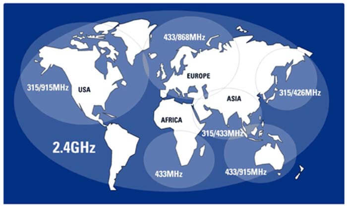
Figure 1 Overview of regional band regulation
What are the interference sources in the 2.4 GHz ISM band?
The 2.4 GHz ISM band has a growing variety of interference sources, including Wi-Fi (IEEE 802.11b/g/n), Bluetooth, cordless phones, analog video, and microwave ovens. The space in which they transmit energy and how that energy is distributed across the band over time varies from device to device.
Interference sources can be broadly classified into two types: standing wave devices and frequency hopping devices. Standing wave interference sources are on the same frequency for a long time and sometimes effectively block other communication signals near this frequency.
Examples include Wi-Fi, microwave ovens, and direct sequence spread spectrum (DSSS) cordless phones. On the other hand, frequency hopping interferers constantly change their operating channels. These sources can cause interference across the entire frequency band without blocking any individual frequency signal for long periods of time.
The DSSS modulation format sends redundant signals that propagate through the spectrum to improve the chances of reconstructing the receiver’s transmitted data in poor communication environments.
This technique is used in WiFi, ZigBee, and other IEEE 802.15.4 networks. IEEE 802.15.4 sends two mega chips of data in a channel with a data rate of 250 Kbps.
Although this modulation format has good resistance to narrowband interference, it is susceptible to interference from other directly superimposed DSSS signals.
In contrast, narrowband frequency hopping spread spectrum (FHSS) modulation signals are more resistant to DSSS signals than other narrowband interferences. FHSS is used in Bluetooth and many dedicated systems.
What is the impact of poor coexistence in the 2.4 GHz ISM band?
If an RF link is susceptible to interference, the packet will be received with some false signals and often packets will be lost. Many bi-directional RF protocols such as IEEE 802.15.4 can guarantee the quality of service in the face of occasional packet loss. They require the receiver to confirm packet reception by transmitting a known ACK (acknowledgment) packet.
If the ACK packet is not received by the transmitter, the original packet is retransmitted. This retransmission continues until the ACK is received correctly or until the transmitter thinks the communication link signal is lost.
One-way RF protocols typically address packet loss by transmitting the same packet multiple times to increase the probability that the packet will reach the receiver intact.
Packet loss due to interference has three main effects: increased latency, increased power consumption, and reduced data throughput capability. An example of increased latency: In a bi-directional ACK system, the first packet is not received correctly due to interference.
The transmitter must wait for an ACK packet from the receiver while a period of downtime occurs before it can assume that the original packet is lost and then send the original packet again.
In a heavily jammed environment and a system susceptible to interference, repeated transmissions such as this may need to be repeated several times to achieve successful communication, thus increasing latency.
The wireless mouse used for drawing circles is a typical example of the extent to which the increased latency caused by poor coexistence can affect the user experience.
In Figure 2, the two 2.4GHz wireless mouse solutions are subject to interference from WiFi file transfers between the computer and a router located 3 meters away from the receiving dongle. The solution on the left clearly suffers from intermittent latency problems.
These problems can be seen in the computer by assuming a straight line and a curved motion between the two coordinates. The solution on the right has good selectivity and uses an adaptive frequency hopping algorithm, which leaves the circle unaffected by the interference.
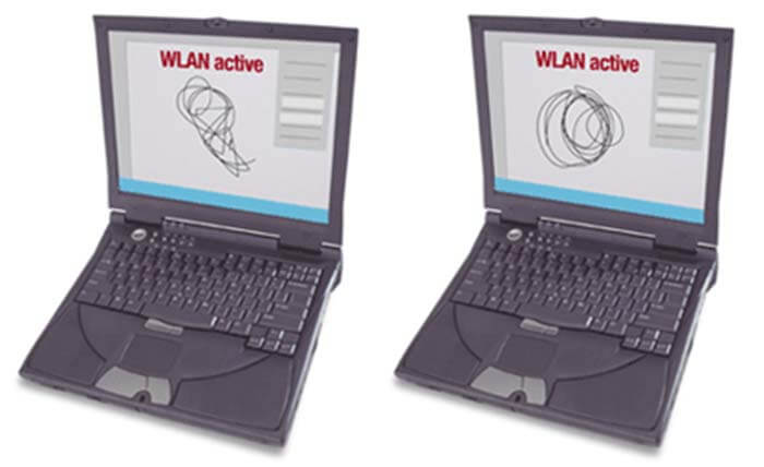
Figure 2 Example of a wireless mouse latency problem caused by interference
Frequent repetitive transmissions can also reduce the total throughput of a high-throughput network. For example, when transmitting audio over an RF link, if interference causes most packet loss, the larger data rate must be reduced to avoid ticking.
How to achieve good coexistence in the 2.4 GHz ISM band?
In some environments, there may be significant interference in some parts of the 2.4 GHz ISM band, while other parts of the band help communication. Frequency hopping or frequency shortcutting algorithms will ensure that the network does not block due to significant interference, and good selectivity will also minimize the interference of communications from other parts of the band.
Selectivity in the 2.4 GHz ISM band
Selectivity in the 2.4 GHz ISM band is a hardware parameter of the receiver; the RF receiver is affected by unwanted signals within the frequency it is trying to receive, and to some extent by the transmission of signals from neighboring frequencies.
As shown in Figure 3, when the target signal is transmitted in a channel that does not overlap with the WiFi channel, the receiver still receives interference from the WiFi transmission.
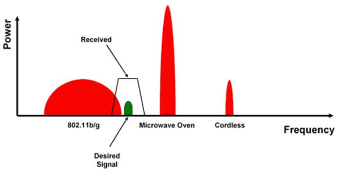
Figure 3 Receiver does not only receive useful signals
Selectivity is a measure of how strongly a receiver can tolerate interference when a packet is received without error when the interfering source transmits in an adjacent channel. Selectivity or interference impedance usually refers to the adjacent channel or interphase channel rejection in dB in the product specification. Figure 4 shows two adjacent channels of interference sources.
Interference sources in both the adjacent and interphase channels are extremely close to each other and can severely interfere with the receiver, eventually leading to packet errors.
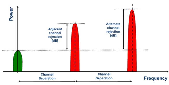
Figure 4 Selectivity is usually measured as adjacent channel and interphase channel suppression
Selectivity in the 2.4 GHz ISM band can also be measured as the proximity of the receiver location to the interfering transmitter without any reduction in sensitivity. As a rule of thumb, every 6 dB increase in selectivity can reduce the distance between the receiver and the interfering transmitter by a factor of two without any reduction in sensitivity.
For example, assuming a peak power consumption of +10 dBm for an interfering transmitter in free space and a target signal frequency of +10 MHz, the shorter distance before the receiver starts to receive interference is
55 dB selectivity: 0.69 m (interfering transmitter signal is: -82 + 55 = -27 dBm)
28 dB selectivity: 15.4 m (interfering transmitter signal: -82 + 28 = -54 dBm)
Wireless standards such as IEEE 802.15.4 set lower requirements for receiver selectivity. These lower requirements should be exceeded if a robust system is to be obtained.
The ZigBee Alliance recently published a white paper on the coexistence of ZigBee and WiFi that highlights the importance of IEEE 802.15.4 for selectivity requirements.
Static Frequency Hopping in the 2.4 GHz ISM band
The 2.4 GHz ISM band Frequency hopping is a method that allows you to constantly change network channels. An example of a frequency hopping algorithm is the implementation of Bluetooth 1.0 and Bluetooth 1.1 technologies.
The master device generates a pseudo-random sequence of channels, uses them in subsequent time slots, and assigns them to network members. The network members can then jump synchronously between the intended channels.
The advantage of this scheme is that the network stays on a single channel for a short period of time, so if there is severe interference in one channel and the communication signal is lost altogether, then it can be retried on another channel in the next time slot.
The disadvantage is that the network must be synchronized because if the network moves into a channel where all communication signals are lost due to interference, the network members will all decide to move to the next channel at the same time.
In addition to the channel list assignment, this increases the software complexity and the total overhead of the network traffic. The disadvantage of this algorithm is that the throughput of the network is reduced by a quarter when a source of interference such as a WiFi network causes a quarter of the available channels in the 2.4 GHz band to be interfered with.
If several heavily interfered channels are selected one after another, the latency can be high.
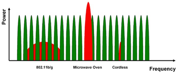
Figure 5 Static in the 2.4 GHz ISM band frequency hopping
Adaptive 2.4 GHz ISM band Frequency Hopping
Adaptive 2.4 GHz ISM band frequency hopping is an enhanced algorithm to the static frequency hopping algorithm. This algorithm allows the system master to remember the undisturbed channels and to use them more frequently.
The master device keeps a data table with a record of the scoring of each channel. This table is constantly updated and upgraded based on the communication quality of the channels.
The selection of which channels need to be jumped to the next channel is generally made deterministically, or by applying a random weighted value based on the scores in the table. The list of channels that will be used next is assigned to each network device.
For many synchronous applications such as keyboard/mouse, remote control, and audio, an adaptive frequency hopping algorithm can be effective in reducing interference, as is the case with Bluetooth 1.2 and RadioDesk.
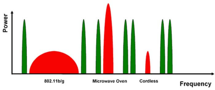
Figure 6 Adaptive 2.4 GHz ISM band Frequency Hopping
What is the 2.4 GHz ISM band Frequency shortcutting?
The 2.4 GHz ISM band frequency shortcutting is an extremely slow frequency hopping algorithm. The network stays on the same channel until the packet error rate (PER) rises above a certain threshold.
In practice, when it finds a channel with very little interference, it stays there until new interference occurs. The advantage of frequency shortcutting is that there is minimal overhead and high throughput when there is a very small change in the interference pattern; however, the general reluctance to change channels when interfered with by a frequency hopping interference source like Bluetooth is a challenge for 2.4 GHz ISM band frequency shortcutting systems.
The system should be patient enough to wait for a frequency hopping source to move to the next channel, and it can continue to transmit quickly when a new static source interferes with the system.
The disadvantage of 2.4 GHz ISM band frequency shortcutting is that when unacceptable interference is detected and the frequency must be changed, the master device has no reliable channel to notify network members that the frequency has changed. Instead, a timeout must be used, for example, and the time delay caused by the frequency change may not be accepted by the user interface system.
Besides this How Do Achieve A Good Coexistence In The 2.4 GHz ISM band article, you may also be interested in the below articles.
What is the difference between WIFI and WLAN?
Summary of 41 Basic Knowledge of LTE
What Is The 5G Network Slicing?