Description
What is a High Gain LTE Antenna 4G PCB Antenna?
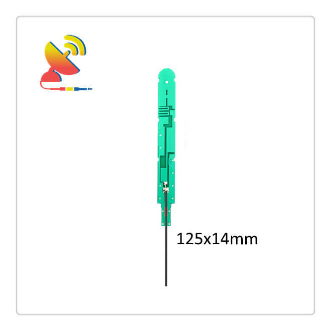
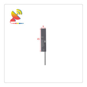
The High Gain LTE Antenna 4G PCB Antenna CTRF-ANTENNA-PCB-7027-12514-IPEX model is an embedded antenna printed circuit board 4G LTE antenna with a 6/8dBi high-gain antenna manufactured by C&T RF Antennas Inc. great for expanding your wireless network and improving your broadcasting or receiving stations.
C&T RF Antennas Inc. offers internal & external antennas for fixed & mobile applications covering cellular & CBRS frequency ranges.
C&T RF Antennas Inc provides internal & external antennas with antenna radio frequencies such as NFC, 169MHz, 230MHz, 315MHz, 433MHz, 868MHz, 915MHz, VHF&UHF, Lora, NB-IoT, ADS-B, GSM, GNSS, GPRS, 1.2 GHz, 1.4 GHz, 1.8 GHz, Wi-Fi 2.4 GHz, 5.8 GHz, Cellular 2G, 3G, 3.5 GHz, 4G LTE, GPS, 5G NR, 6G, etc.
C&T RF Antennas Inc. provides RF antennae with Omni & Directional antenna types such as Dipole Antennas, Whip Antennas, Marine Antennas, Router Antennas, MIMO Antennas, Combo Antennas, PCB Antennas, FPC Antennas, Spring Antennas, Magnetic Antennas, Sector Antennas, Yagi Antennas, and Accessories, etc, for IoT & M2M industries.
Contact us for the High-gain LTE Antenna 4G PCB Antenna for more details such as High-gain LTE Antenna 4G PCB Antenna datasheet, Antenna 4G PCB Antenna pricing, Antenna 4G PCB Antenna inventory, or other Antenna 4G PCB Antenna types.
High Gain LTE Antenna 4G PCB Antenna Specifications:
High Gain LTE 3G Antenna 4G PCB Electrical Specifications |
|
| RF Antenna Type | Built-in PCB Antenna |
| Model | CTRF-ANTENNA-PCB-7027-12514-IPEX |
| Frequency | 698-960MHz, 1710-2700MHz |
| Gain | 6dBi/8dBi |
| VSWR | ≤2.5 |
| Impedance | 50 Ω |
| Polarization | Vertical/Linear |
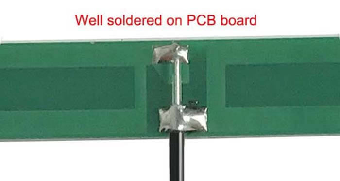
| Cable Type | RG1.13 |
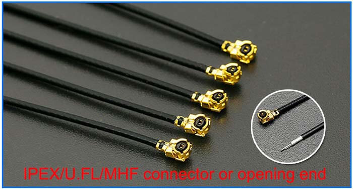
| Connector | U.FL/IPEX |
| Cable Length | 100mm |
| Lightning Protection | DC-Ground |
High Gain LTE 3G Antenna 4G PCB Antenna Mechanical Specifications |
|
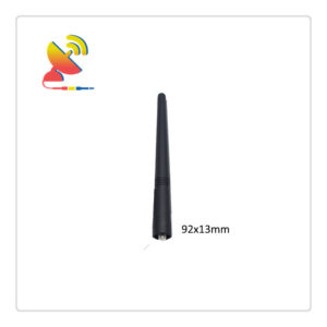
| PCB Board Dimension | 125*14mm |
| Weight | Approx. 8g |
| Material | PCB + RG Cable + U.FL connector |
| Operation Temperature | -40˚C ~ +65˚C |
| Storage Temperature | -40˚C ~ +70˚C |
| Color | Green |
| Antenna Design | Dipole Antenna |
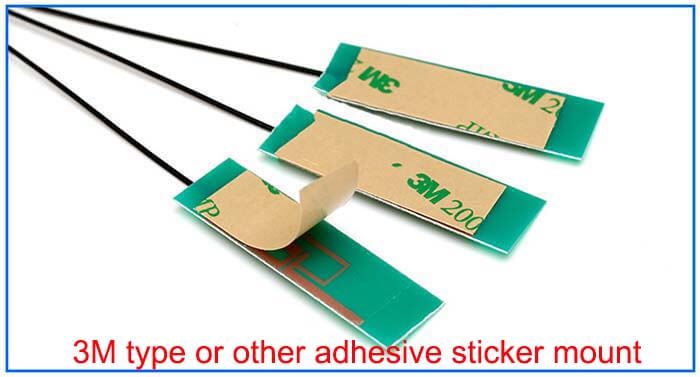
| Mounting | Connector/Peel-and-stick |
| Safety Emission and other | RoHS Compliant |
| Applications | ISM/SCADA/Utilities, IoT/M2M/NB-IoT/LoRa, 2G 3G 4G LTE/LTE-IoT, GSM GPRS UMTS, etc. |
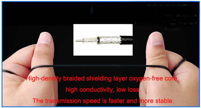
Antenna 4G PCB Antenna Features
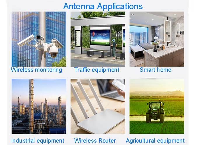
Antenna 4G PCB Applications
Antenna 4G PCB Antenna Design
First, the antenna design is not simple.
Even with modeling programs like digital electromagnetic codes, circuits, or systems engineers are unfamiliar with the electromagnetic world. They are facing a world of electromagnetic fields, not specific voltage and current points or electron currents flowing in a fixed loop.
Secondly, as with many engineering designs, competing and conflicting attributes such as center frequency, bandwidth, field mode, efficiency, and lobe and gain make it difficult to balance them.
Third, it is not easy to evaluate the performance of an antenna. It requires special test equipment, a non-reflective chamber, or an open area. It also requires time, money, and expertise.
In addition, when evaluating the impact of the user’s hand on the antenna, or vice versa, when evaluating the impact of antenna radiation on the user’s hand, correct test settings must be performed, including the physical copy of the human hand and head.
And these are all theoretical. In fact, there are other factors at play. The antenna certainly occupies the PCB space, and its performance attributes are significantly affected by nearby components and the user’s hands, head, and body.
The relative dielectric constant of human tissue is 40, and the dielectric constant of PCB components is about 25 to 85, so human tissue will excite resonance elements and affect the magnetic field.
In addition, when multiple antennas are required for multi-band operation or shape diversity design, the interaction between several PCB antennas and between antennas and nearby areas will make performance prediction very difficult, and they are sensitive to subtle layout changes.
But there are also rules that constrain the antenna field-specific absorption rate (SAR). SAR is the ratio of mass (human tissue in this case) to the ability to absorb RF;
Usually, two methods are used to measure it: one is to measure the temperature rise due to absorption; the other is to measure the electric field of the fluid that simulates human tissue.
There is more information on the Federal Communications Commission (FCC) website. The near-field and far-field performance of the antenna must be understood and analyzed, and they may be closely related.
Finally, the antenna is not isolated from the front end of the wireless device or the transmit power amplifier stage. The circuit designer must determine the impedance of the antenna and associated stages, and then design a matching network to maximize power transfer across the target bandwidth.
C&T RF Antennas Inc. is an antenna PCB manufacturer who can help you with the PCB antenna design and manufacture, welcome to send the PCB file to info@ctrfantennasinc.com to get a quote now!
Reviews
There are no reviews yet.